

1 Executive Summary
Compute virtualization and converged infrastructure has introduced tremendous changes in Data Center networks. Traditional network design (Core, Aggregation and Access layers) coupled with Spanning tree protocol for management of layer 2 loops could not simply afford requirements of virtual machine mobility and elephant flows required for modern applications. All major network vendors have collaborated and brought new technologies to solve modern day Data Center challenges. 3 tier traditional networks are being replaced with flat switching fabric or scalable IP-Fabric.
2 Multi-Chassis LAG, A Solution
Multi-Chassis Link Aggregation Group is another solution besides “Switching Fabric and IP Fabric” where access devices or servers can have active-active connectivity and traffic load sharing on links connected with 2 different network devices. The basic idea is to prune effects of spanning tree protocol and offer active-active topology and redundancy for link and device safe fail-over.
In this solution paper; we will discuss how to design a Data Center network for small to medium organization with collapsed core architecture (Core and aggregation layers combined in single layer) with active-active multi-homing between server and access layer switches and active-active multi-homing between access and core layer network devices. Thus completely removing spanning tree within Data Center while all switches have active control and forwarding plane with end to end device and link level redundancy.
The question arises why do we need MC-LAG when already other high availability solution (e.g Juniper Virtual Chassis or Cisco VSS) exists. Out of several reasons few important ones are listed below: –
- Juniper Virtual Chassis or Cisco VSS depends on specific type of merchant chip-set (usually supplied by Broadcom), Virtual Chassis feature may not be supported or not stable on customized chip-set (e.g Juniper One –Used in EX 9200, Q5 used in Juniper QFX 10k and Trio chip-set used in Juniper MX router)
- Virtual Chassis offers us only 1 active control plane with multiple forwarding plane while MC-LAG not only offers us active-active forwarding plane but also offers active-active control plane in both MC-LAG peers.
- MC-LAG is good choice once we are not deploying green field Data Center and needs to upgrade either Core or access layer switches in production data center and need to integrate switches from mutli-vendor at different layers.
3 Reference Topology
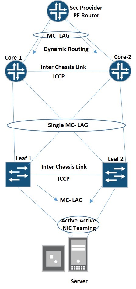
Note: Multi-stage MC-LAG is high scaleable, max no of leaf devices depends on of ports available on spine or core nodes
4 Connectivity Description
4.1 Server to Access Switches Connectivity
Server has dual link connected to two separate leaf devices (access layer switches). Both links of server will participate in topology in active-active mode although they are connected with two separate switches. In order to prevent layer 2 loops between server and access switches Multi-Chassis LAG (MC-LAG) will be configured on Leaf 1 and Leaf 2 and server will not come to know that it is connected with two separate devices.
4.2 Leaf to Leaf Connectivity
Leaf 1 and Leaf 2 will run Inter Chassis Control Protocol (ICCP) to exchange control states and for configuration synch checks. Moreover, Inter-Chassis link will span all VLANs between 2 leaf devices in order to exchange forwarding plane states. Ae0 will be used to span all VLANs between Leaf 1 and Leaf 2.
4.3 Access Layer to Core Layer
Each Leaf devices is connected with each core device thus forming cross connectivity among leaf and core devices. Single MC-LAG is configured between core devices and leaf devices, thus providing all active link topology with in Data Center.
4.4 Server VLAN Gateways
Layer 3 interface for all server VLAN will be configured at core layer, however question remains how to provide single gateway for a VLAN as both core switches have separate layer 3 interface for each VLAN. VRRP came to our rescue here and each VLAN will be configured with virtual IP (VIP) address but problem still remains as VRRP can have only one active gateway. But Juniper provide us options to configure Active-Active MC-LAG where both gateway nodes can accept and process traffic.
4.5 Core Layer to DC-Edge
Core layer needs connectivity with service provider network (DC Edge/ PE device) for exchange of data to other Data Center or access to internet. MC-LAG will also be configured between DC Core layer and Svc Provider PE router. With VRRP over IRB and active-active MC-LAG both core nodes can form dynamic routing relationship with PE router and thus can exchange routing information with Svc Provider network (using OSPF / BGP). Svc Provider PE router will see both core nodes as 2 separate next hops and can do traffic load balancing on links connected with Core 1 and Core 2.
4.6 All Active-Active Links
All links starting from sever terminating at leaf nodes, connecting leaf nodes to core nodes and link between core nodes and Svc Provider PE router; are actively participating in the topology thus leaving no link un-utilized. VRRP over IRB at Core layer and Juniper Active-Active MC-LAG arrangements enables both core nodes to process or load balance layer 3 traffic coming either from Svc provider DC-Edge router or sever traffic coming through leaf nodes.
5 Configuration
5.1 Leaf -1
Set system host-name Leaf-1
set chassis aggregated-devices ethernet device-count 3
set interfaces ae0 aggregated-ether-options lacp active #Inter Chassis link
set interfaces ae0 unit 0 family ethernet-switching interface-mode trunk
set interfaces ae0 unit 0 family ethernet-switching vlan members 10-12 #data vlans
set interfaces ae0 unit 0 family ethernet-switching vlan members 254 #VLAN carrying ICCP traffic
set interfaces xe-0/0/0 ether-options 802.3ad ae0
set vlans vl10 vlan-id 10
set vlans vl11 vlan-id 11
set vlans vl12 vlan-id 12
set vlans vl254 vlan-id 254
set vlans vl254 l3-interface irb.100
set interfaces irb unit 100 family inet address 10.10.1.1/30 # MC-LAG peer establish OSPF neighbor ship
set interfaces lo0 unit 0 family inet address 2.2.2.1/32 #ICCP session will be established over lo0.0 IP
set protocols ospf area 0.0.0.0 interface irb.100
set protocols ospf area 0.0.0.0 interface lo0.0
set protocols iccp local-ip-addr 2.2.2.1 #ICCP configuration
set protocols iccp local-ip-addr 2.2.2.1
set protocols iccp peer 2.2.2.1 session-establishment-hold-time 50
set protocols iccp peer 2.2.2.2 redundancy-group-id-list 1 #service ID will be used here
set protocols iccp peer 2.2.2.2 liveness-detection minimum-interval 500
set multi-chassis multi-chassis-protection 2.2.2.2 interface ae0
set switch-options service-id 1
set interfaces ae2 description to-Server-1
set interfaces ae2 aggregated-ether-options lacp active
set interfaces ae2 aggregated-ether-options lacp periodic fast
set interfaces ae2 aggregated-ether-options lacp system-id 00:00:00:00:00:11 #must match on MC-LAG peers
set interfaces ae2 aggregated-ether-options lacp admin-key 11 # must match on MC-LAG peers
set interfaces ae2 aggregated-ether-options mc-ae mc-ae-id 11 # must match on MC-LAG peers
set interfaces ae2 aggregated-ether-options mc-ae redundancy-group 1 # must match on MC-LAG peers
set interfaces ae2 aggregated-ether-options mc-ae chassis-id 0 # must differ on MC-LAG peers
set interfaces ae2 aggregated-ether-options mc-ae mode active-active #always active-active
set interfaces ae2 aggregated-ether-options mc-ae status-control active #Only one node in active
set interfaces xe-0/0/1 ether-options 802.3ad ae2
set interfaces ae1 description to-Core-Layer
set interfaces ae1 aggregated-ether-options lacp active
set interfaces ae1 aggregated-ether-options lacp periodic fast
set interfaces ae1 aggregated-ether-options lacp system-id 00:00:00:00:00:10
set interfaces ae1 aggregated-ether-options lacp admin-key 10
set interfaces ae1 aggregated-ether-options mc-ae mc-ae-id 10
set interfaces ae1 aggregated-ether-options mc-ae redundancy-group 1
set interfaces ae1 aggregated-ether-options mc-ae chassis-id 0
set interfaces ae1 aggregated-ether-options mc-ae mode active-active
set interfaces ae1 aggregated-ether-options mc-ae status-control active
set interfaces ae1 unit 0 family ethernet-switching interface-mode trunk
set interfaces ae1 unit 0 family ethernet-switching vlan members 10-12
set interfaces xe-0/0/2 ether-options 802.3ad ae1
set interfaces xe-0/0/2 description Connected with-Core-1
set interfaces xe-0/0/3 ether-options 802.3ad ae1
set interfaces xe-0/0/3 description Connected with-Core-2
5.2 Leaf 2
Set system host-name Leaf-2
set chassis aggregated-devices ethernet device-count 3
set interfaces ae0 aggregated-ether-options lacp active #Inter Chassis link
set interfaces ae0 unit 0 family ethernet-switching interface-mode trunk
set interfaces ae0 unit 0 family ethernet-switching vlan members 10-12 #data vlans
set interfaces ae0 unit 0 family ethernet-switching vlan members 254 #VLAN carrying ICCP traffic
set interfaces xe-0/0/0 ether-options 802.3ad ae0
set vlans vl10 vlan-id 10
set vlans vl11 vlan-id 11
set vlans vl12 vlan-id 12
set vlans vl254 vlan-id 254
set vlans vl254 l3-interface irb.100
set interfaces irb unit 100 family inet address 10.10.1.2/30 # MC-LAG establish OSPF neighbor ship
set interfaces lo0 unit 0 family inet address 2.2.2.2/32 #ICCP session will be established over lo0.0 IP
set protocols ospf area 0.0.0.0 interface irb.100
set protocols iccp local-ip-addr 2.2.2.2 #ICCP configuration
set protocols iccp peer 2.2.2.1 session-establishment-hold-time 50
set protocols iccp peer 2.2.2.1 redundancy-group-id-list 1
set protocols iccp peer 2.2.2.1 liveness-detection minimum-interval 500
set switch-options service-id 1
set multi-chassis multi-chassis-protection 2.2.2.1 interface ae0
set interfaces ae2 description to-Server-1
set interfaces ae2 aggregated-ether-options lacp active
set interfaces ae2 aggregated-ether-options lacp periodic fast
set interfaces ae2 aggregated-ether-options lacp system-id 00:00:00:00:00:11
set interfaces ae2 aggregated-ether-options lacp admin-key 11
set interfaces ae2 aggregated-ether-options mc-ae mc-ae-id 11
set interfaces ae2 aggregated-ether-options mc-ae redundancy-group 1
set interfaces ae2 aggregated-ether-options mc-ae chassis-id 1
set interfaces ae2 aggregated-ether-options mc-ae mode active-active
set interfaces ae2 aggregated-ether-options mc-ae status-control standby #Must differ on MC-LAG peers
set interfaces xe-0/0/1 ether-options 802.3ad ae2
set interfaces ae1 description to-Core-Layer
set interfaces ae1 aggregated-ether-options lacp active
set interfaces ae1 aggregated-ether-options lacp periodic fast
set interfaces ae1 aggregated-ether-options lacp system-id 00:00:00:00:00:10
set interfaces ae1 aggregated-ether-options lacp admin-key 10
set interfaces ae1 aggregated-ether-options mc-ae mc-ae-id 10
set interfaces ae1 aggregated-ether-options mc-ae redundancy-group 1
set interfaces ae1 aggregated-ether-options mc-ae chassis-id 1
set interfaces ae1 aggregated-ether-options mc-ae mode active-active
set interfaces ae1 aggregated-ether-options mc-ae status-control standby
set interfaces ae1 unit 0 family ethernet-switching interface-mode trunk
set interfaces ae1 unit 0 family ethernet-switching vlan members 10-12
set interfaces xe-0/0/2 ether-options 802.3ad ae1
set interfaces xe-0/0/2 description Connected-with-Core-1
set interfaces xe-0/0/3 ether-options 802.3ad ae1
set interfaces xe-0/0/3 description Connected-with-Core-2
5.3 Core-1
set system host-name Core-1
set chassis aggregated-devices ethernet device-count 3
set interfaces ae0 aggregated-ether-options lacp active #Inter Chassis link
set interfaces ae0 unit 0 family bridge interface-mode trunk
set interfaces ae0 unit 0 family bridge vlan-id-list 10-12
set interfaces ae0 unit 0 family bridge vlan-id-list 254
set interfaces ae0 unit 0 family bridge vlan-id-list 200
set interfaces xe-0/0/0 gigether-options 802.3ad ae0
set interfaces xe-0/0/1 gigether-options 802.3ad ae0
set bridge-domains bd10 vlan-id 10
set bridge-domains bd10 routing-interface irb.10
set bridge-domains bd11 vlan-id 11
set bridge-domains bd12 vlan-id 12
set bridge-domains bd12 routing-interface irb.12
set bridge-domains bd200 vlan-id 200
set bridge-domains bd200 routing-interface irb.200
set bridge-domains bd254 vlan-id 254
set bridge-domains bd254 routing-interface irb.254
#layer 3 interface for each VLAN , VRRP configured to provide VIP for each subnet
set interfaces irb unit 10 family inet address 1.1.10.1/24 vrrp-group 10 virtual-address 1.1.10.1
set interfaces irb unit 10 family inet address 1.1.10.1/24 vrrp-group 10 priority 255
set interfaces irb unit 10 family inet address 1.1.10.1/24 vrrp-group 10 accept-data
set interfaces irb unit 11 family inet address 1.1.11.1/24 vrrp-group 11 virtual-address 1.1.11.1
set interfaces irb unit 11 family inet address 1.1.11.1/24 vrrp-group 11 priority 255
set interfaces irb unit 11 family inet address 1.1.11.1/24 vrrp-group 11 accept-data
set interfaces irb unit 12 family inet address 1.1.12.1/24 vrrp-group 12 virtual-address 1.1.12.1
set interfaces irb unit 12 family inet address 1.1.12.1/24 vrrp-group 12 priority 255
set interfaces irb unit 12 family inet address 1.1.12.1/24 vrrp-group 12 accept-data
#ICCP Configuration
set interfaces irb unit 254 family inet address 100.100.100.1/30
set interfaces lo0 unit 0 family inet address 1.1.1.1/32
set protocols ospf area 0.0.0.0 interface irb.254 #OSPF on physical interface connected with Core-2
set protocols ospf area 0.0.0.0 interface lo0.0
set protocols iccp local-ip-addr 1.1.1.1
set protocols iccp peer 1.1.1.2 session-establishment-hold-time 50
set protocols iccp peer 1.1.1.2 redundancy-group-id-list 1 #Must match service-ID value
set protocols iccp peer 1.1.1.2 liveness-detection minimum-interval 800
set multi-chassis multi-chassis-protection 1.1.1.2 interface ae0
set switch-options service-id 1
set interfaces ae1 description to-Leaf
set interfaces ae1 aggregated-ether-options lacp active
set interfaces ae1 aggregated-ether-options lacp periodic fast
set interfaces ae1 aggregated-ether-options lacp system-id 00:00:00:00:00:01
set interfaces ae1 aggregated-ether-options lacp admin-key 1
set interfaces ae1 aggregated-ether-options mc-ae mc-ae-id 1
set interfaces ae1 aggregated-ether-options mc-ae redundancy-group 1
set interfaces ae1 aggregated-ether-options mc-ae chassis-id 0
set interfaces ae1 aggregated-ether-options mc-ae mode active-active
set interfaces ae1 aggregated-ether-options mc-ae status-control active
set interfaces ae1 unit 0 family bridge interface-mode trunk
set interfaces ae1 unit 0 family bridge vlan-id-list 10-12
set interfaces xe-0/0/2 gigether-options 802.3ad ae1
set interfaces xe-0/0/2 description to-Leaf-1
set interfaces xe-0/0/3 gigether-options 802.3ad ae1
set interfaces xe-0/0/3 description to-Leaf-2
set interfaces ae2 description to-DC-Edge
set interfaces ae2 aggregated-ether-options lacp active
set interfaces ae2 aggregated-ether-options lacp periodic fast
set interfaces ae2 aggregated-ether-options lacp system-id 00:00:00:00:00:02
set interfaces ae2 aggregated-ether-options lacp admin-key 2
set interfaces ae2 aggregated-ether-options mc-ae mc-ae-id 2
set interfaces ae2 aggregated-ether-options mc-ae redundancy-group 1
set interfaces ae2 aggregated-ether-options mc-ae chassis-id 0
set interfaces ae2 aggregated-ether-options mc-ae mode active-active
set interfaces ae2 aggregated-ether-options mc-ae status-control active
set interfaces ae2 unit 0 family bridge interface-mode access
set interfaces ae2 unit 0 family bridge vlan-id 200
set interfaces xe-0/0/5 gigether-options 802.3ad ae2
#IRB.200 will be used to form dynamic routing with DC-Edge (BGP in our case)
set interfaces irb unit 200 family inet address 200.200.200.2/29 vrrp-group 200 virtual-address 200.200.200.1
set interfaces irb unit 200 family inet address 200.200.200.2/29 vrrp-group 200 priority 200
set interfaces irb unit 200 family inet address 200.200.200.2/29 vrrp-group 200 accept-data
#IRB which needs to run Dynamic routing always need static ARP entry , mac address of opposite core device IRB will be used to bind static APR , show interface irb can be used to get mac on opposite MC-LAG peer device.
set interfaces irb unit 200 family inet address 200.200.200.2/29 arp 200.200.200.3 l2-interface ae0.0
set interfaces irb unit 200 family inet address 200.200.200.2/29 arp 200.200.200.3 mac 00:05:86:94:9b:f0
EBGP Configuration with DC-Edge
set protocols bgp group DC peer-as 65000
set protocols bgp group DC local-as 65001
set protocols bgp group DC neighbor 200.200.200.4 local-address 200.200.200.2
#iBGP Configuration with Core-2
set protocols bgp group iBG type internal
set protocols bgp group iBG local-address 200.200.200.2
set protocols bgp group iBG peer-as 65001
set protocols bgp group iBG local-as 65001
set protocols bgp group iBG neighbor 200.200.200.3
#Exporting server subnets to DC-Edge
set protocols bgp group DC export to-bgp
set policy-options policy-statement to-bgp term 1 from protocol direct
set policy-options policy-statement to-bgp term 1 from route-filter 10.10.20.0/24 exact #rejecting fxp0 to be advertise
set policy-options policy-statement to-bgp term 1 then reject
set policy-options policy-statement to-bgp term 2 from protocol direct
set policy-options policy-statement to-bgp term 2 from route-filter 0.0.0.0/0 prefix-length-range /24-/24
set policy-options policy-statement to-bgp term 2 then accept
5.4 Core-2
set system host-name Core-2
set chassis aggregated-devices ethernet device-count 3
set interfaces ae0 aggregated-ether-options lacp active #Inter Chassis link
set interfaces ae0 unit 0 family bridge interface-mode trunk
set interfaces ae0 unit 0 family bridge vlan-id-list 10-12
set interfaces ae0 unit 0 family bridge vlan-id-list 254
set interfaces ae0 unit 0 family bridge vlan-id-list 200
set interfaces xe-0/0/0 gigether-options 802.3ad ae0
set interfaces xe-0/0/1 gigether-options 802.3ad ae0
set bridge-domains bd10 vlan-id 10
set bridge-domains bd10 routing-interface irb.10
set bridge-domains bd11 vlan-id 11
set bridge-domains bd12 vlan-id 12
set bridge-domains bd12 routing-interface irb.12
set bridge-domains bd200 vlan-id 200
set bridge-domains bd200 routing-interface irb.200
set bridge-domains bd254 vlan-id 254
set bridge-domains bd254 routing-interface irb.254
#layer 3 interface for each VLAN , VRRP configured to provide VIP for each subnet
set interfaces irb unit 10 family inet address 1.1.10.2/24 vrrp-group 10 virtual-address 1.1.10.1
set interfaces irb unit 10 family inet address 1.1.10.2/24 vrrp-group 10 priority 200
set interfaces irb unit 10 family inet address 1.1.10.2/24 vrrp-group 10 accept-data
set interfaces irb unit 11 family inet address 1.1.11.2/24 vrrp-group 11 virtual-address 1.1.11.1
set interfaces irb unit 11 family inet address 1.1.11.2/24 vrrp-group 11 priority 200
set interfaces irb unit 11 family inet address 1.1.11.2/24 vrrp-group 11 accept-data
set interfaces irb unit 12 family inet address 1.1.12.2/24 vrrp-group 12 virtual-address 1.1.12.1
set interfaces irb unit 12 family inet address 1.1.12.2/24 vrrp-group 12 priority 200
set interfaces irb unit 12 family inet address 1.1.12.2/24 vrrp-group 12 accept-data
#ICCP Configuration
set interfaces irb unit 254 family inet address 100.100.100.2/30
set interfaces lo0 unit 0 family inet address 1.1.1.2/32
set protocols ospf area 0.0.0.0 interface irb.254 #OSPF on physical interface connected with Core-2
set protocols ospf area 0.0.0.0 interface lo0.0
set protocols iccp local-ip-addr 1.1.1.2
set protocols iccp peer 1.1.1.1 session-establishment-hold-time 50
set protocols iccp peer 1.1.1.1 redundancy-group-id-list 1 #Must match service-ID value
set protocols iccp peer 1.1.1.1 liveness-detection minimum-interval 800
set multi-chassis multi-chassis-protection 1.1.1.1 interface ae0
set switch-options service-id 1
set interfaces ae1 description to-Leaf
set interfaces ae1 aggregated-ether-options lacp active
set interfaces ae1 aggregated-ether-options lacp periodic fast
set interfaces ae1 aggregated-ether-options lacp system-id 00:00:00:00:00:01
set interfaces ae1 aggregated-ether-options lacp admin-key 1
set interfaces ae1 aggregated-ether-options mc-ae mc-ae-id 1
set interfaces ae1 aggregated-ether-options mc-ae redundancy-group 1
set interfaces ae1 aggregated-ether-options mc-ae chassis-id 1
set interfaces ae1 aggregated-ether-options mc-ae mode active-active
set interfaces ae1 aggregated-ether-options mc-ae status-control standby
set interfaces ae1 unit 0 family bridge interface-mode trunk
set interfaces ae1 unit 0 family bridge vlan-id-list 10-12
set interfaces xe-0/0/2 gigether-options 802.3ad ae1
set interfaces xe-0/0/2 description to-Leaf-1
set interfaces xe-0/0/3 gigether-options 802.3ad ae1
set interfaces xe-0/0/3 description to-Leaf-2
set interfaces ae2 description to-DC-Edge
set interfaces ae2 aggregated-ether-options lacp active
set interfaces ae2 aggregated-ether-options lacp periodic fast
set interfaces ae2 aggregated-ether-options lacp system-id 00:00:00:00:00:02
set interfaces ae2 aggregated-ether-options lacp admin-key 2
set interfaces ae2 aggregated-ether-options mc-ae mc-ae-id 2
set interfaces ae2 aggregated-ether-options mc-ae redundancy-group 1
set interfaces ae2 aggregated-ether-options mc-ae chassis-id 1
set interfaces ae2 aggregated-ether-options mc-ae mode active-active
set interfaces ae2 aggregated-ether-options mc-ae status-control standby
set interfaces ae2 unit 0 family bridge interface-mode access
set interfaces ae2 unit 0 family bridge vlan-id 200
set interfaces xe-0/0/5 gigether-options 802.3ad ae2
#IRB.200 will be used to form dynamic routing with DC-Edge (BGP in our case)
set interfaces irb unit 200 family inet address 200.200.200.3/29 arp 200.200.200.2 l2-interface ae0.0
set interfaces irb unit 200 family inet address 200.200.200.3/29 vrrp-group 200 virtual-address 200.200.200.1
set interfaces irb unit 200 family inet address 200.200.200.3/29 vrrp-group 200 priority 100
set interfaces irb unit 200 family inet address 200.200.200.3/29 vrrp-group 200 accept-data
#IRB which needs to run Dynamic routing always need static ARP entry , mac address of opposite core device IRB will be used to bind static APR , show interface irb can be used to get mac on opposite MC-LAG peer device.
set interfaces irb unit 200 family inet address 200.200.200.3/29 arp 200.200.200.2 mac 00:05:86:72:fb:f0
#EBGP Configuration with DC-Edge
set protocols bgp group DC1 local-address 200.200.200.3
set protocols bgp group DC1 export to-bgp
set protocols bgp group DC1 peer-as 65000
set protocols bgp group DC1 local-as 65001
set protocols bgp group DC1 neighbor 200.200.200.4
#iBGP Configuration with Core-1
set protocols bgp group iBGP peer-as 65001
set protocols bgp group iBGP local-as 65001
set protocols bgp group iBGP neighbor 200.200.200.2 local-address 200.200.200.3
#Exporting server subnets to DC-Edge
set policy-options policy-statement to-bgp term 1 from protocol direct
set policy-options policy-statement to-bgp term 1 from route-filter 10.10.20.0/24 exact
set policy-options policy-statement to-bgp term 1 then reject
set policy-options policy-statement to-bgp term 2 from protocol direct
set policy-options policy-statement to-bgp term 2 from route-filter 0.0.0.0/0 prefix-length-range /24-/24
set policy-options policy-statement to-bgp term 2 then accept
6 Verifications
6.1 Leaf 1
root@Leaf-1> show iccp
Redundancy Group Information for peer 2.2.2.2
TCP Connection : Established
Liveliness Detection : Up
Redundancy Group ID Status
1 Up
Client Application: lacpd
Redundancy Group IDs Joined: 1
Client Application: MCSNOOPD
Redundancy Group IDs Joined: None
Client Application: l2ald_iccpd_client
Redundancy Group IDs Joined: 1
root@Leaf-1> show lacp interfaces ae0 #Inter Chassis link
Aggregated interface: ae0
LACP state: Role Exp Def Dist Col Syn Aggr Timeout Activity
xe-0/0/0 Actor No No Yes Yes Yes Yes Fast Active
xe-0/0/0 Partner No No Yes Yes Yes Yes Fast Active
LACP protocol: Receive State Transmit State Mux State
xe-0/0/0 Current Fast periodic Collecting distributing
root@Leaf-1> show lacp statistics interfaces ae0 #Inter Chassis link
Aggregated interface: ae0
LACP Statistics: LACP Rx LACP Tx Unknown Rx Illegal Rx
xe-0/0/0 1301 1287 0 0
root@Leaf-1> show lacp interfaces ae1
Aggregated interface: ae1
LACP state: Role Exp Def Dist Col Syn Aggr Timeout Activity
xe-0/0/2 Actor No No Yes Yes Yes Yes Fast Active
xe-0/0/2 Partner No No Yes Yes Yes Yes Fast Active
xe-0/0/3 Actor No No Yes Yes Yes Yes Fast Active
xe-0/0/3 Partner No No Yes Yes Yes Yes Fast Active
LACP protocol: Receive State Transmit State Mux State
xe-0/0/2 Current Fast periodic Collecting distributing
xe-0/0/3 Current Fast periodic Collecting distributing
root@Leaf-1> show lacp statistics interfaces ae1
#ae1 member interfaces connected to two different core devices and actively receiving/ sending LACP packets, same can also be verified on Leaf-2.
Aggregated interface: ae1
LACP Statistics: LACP Rx LACP Tx Unknown Rx Illegal Rx
xe-0/0/2 323 1291 0 0 #Interface connected to Core-1
xe-0/0/3 128 1289 0 0 #Interface connected to Core-2
root@Leaf-1> show lacp interfaces ae2 #Interface connected with Server-1
Aggregated interface: ae2
LACP state: Role Exp Def Dist Col Syn Aggr Timeout Activity
xe-0/0/1 Actor No No Yes Yes Yes Yes Fast Active
xe-0/0/1 Partner No No Yes Yes Yes Yes Fast Active
LACP protocol: Receive State Transmit State Mux State
xe-0/0/1 Current Fast periodic Collecting distributing
root@Leaf-1> show lacp statistics interfaces ae2
#ae2 member interface connected to server sending/ receiving packet, same can be verified on Leaf-1.
Aggregated interface: ae2
LACP Statistics: LACP Rx LACP Tx Unknown Rx Illegal Rx
xe-0/0/1 58 1287 0 0
6.2 Leaf 2
root@Leaf-2> show iccp
Redundancy Group Information for peer 2.2.2.1
TCP Connection : Established
Liveliness Detection : Up
Redundancy Group ID Status
1 Up
Client Application: lacpd
Redundancy Group IDs Joined: 1
Client Application: MCSNOOPD
Redundancy Group IDs Joined: None
Client Application: l2ald_iccpd_client
Redundancy Group IDs Joined: 1
root@Leaf-2> show lacp interfaces ae0 #Inter chassis link
Aggregated interface: ae0
LACP state: Role Exp Def Dist Col Syn Aggr Timeout Activity
xe-0/0/0 Actor No No Yes Yes Yes Yes Fast Active
xe-0/0/0 Partner No No Yes Yes Yes Yes Fast Active
LACP protocol: Receive State Transmit State Mux State
xe-0/0/0 Current Fast periodic Collecting distributing
root@Leaf-2> show lacp statistics interfaces ae0
Aggregated interface: ae0
LACP Statistics: LACP Rx LACP Tx Unknown Rx Illegal Rx
xe-0/0/0 1271 1296 0 0
root@Leaf-2> show lacp interfaces ae1 #link connected to Core-1 and Core-2
Aggregated interface: ae1
LACP state: Role Exp Def Dist Col Syn Aggr Timeout Activity
xe-0/0/2 Actor No No Yes Yes Yes Yes Fast Active
xe-0/0/2 Partner No No Yes Yes Yes Yes Fast Active
xe-0/0/3 Actor No No Yes Yes Yes Yes Fast Active
xe-0/0/3 Partner No No Yes Yes Yes Yes Fast Active
LACP protocol: Receive State Transmit State Mux State
xe-0/0/2 Current Fast periodic Collecting distributing
xe-0/0/3 Current Fast periodic Collecting distributing
root@Leaf-2> show lacp statistics interfaces ae1
#ae1 member interfaces connected to two different core devices and actively receiving/ sending LACP packets, same can also be verified on Leaf-1.
Aggregated interface: ae1
LACP Statistics: LACP Rx LACP Tx Unknown Rx Illegal Rx
xe-0/0/2 113 1296 0 0
xe-0/0/3 306 1296 0 0
root@Leaf-2> show lacp interfaces ae2 # link connected to server
Aggregated interface: ae2
LACP state: Role Exp Def Dist Col Syn Aggr Timeout Activity
xe-0/0/1 Actor No No Yes Yes Yes Yes Fast Active
xe-0/0/1 Partner No No Yes Yes Yes Yes Fast Active
LACP protocol: Receive State Transmit State Mux State
xe-0/0/1 Current Fast periodic Collecting distributing
root@Leaf-2> show lacp statistics interfaces ae2
#ae2 member interface connected to server sending/ receiving packet, same can be verified on Leaf-1.
Aggregated interface: ae2
LACP Statistics: LACP Rx LACP Tx Unknown Rx Illegal Rx
xe-0/0/1 44 1296 0 0
6.3 Core-1
root@Core-1> show iccp
Redundancy Group Information for peer 1.1.1.2
TCP Connection : Established
Liveliness Detection : Up
Redundancy Group ID Status
1 Up
Client Application: lacpd
Redundancy Group IDs Joined: 1
Client Application: l2ald_iccpd_client
Redundancy Group IDs Joined: 1
root@Core-1> show lacp interfaces ae0 #Inter Chassis link
Aggregated interface: ae0
LACP state: Role Exp Def Dist Col Syn Aggr Timeout Activity
xe-0/0/0 Actor No No Yes Yes Yes Yes Fast Active
xe-0/0/0 Partner No No Yes Yes Yes Yes Fast Active
xe-0/0/1 Actor No No Yes Yes Yes Yes Fast Active
xe-0/0/1 Partner No No Yes Yes Yes Yes Fast Active
LACP protocol: Receive State Transmit State Mux State
xe-0/0/0 Current Fast periodic Collecting distributing
xe-0/0/1 Current Fast periodic Collecting distributing
root@Core-1> show lacp statistics interfaces ae0
Aggregated interface: ae0
LACP Statistics: LACP Rx LACP Tx Unknown Rx Illegal Rx
xe-0/0/0 183 378 0 0
xe-0/0/1 182 373 0 0
root@Core-1> show lacp interfaces ae1 #Link connected with Leaf-1 and Leaf-2
Aggregated interface: ae1
LACP state: Role Exp Def Dist Col Syn Aggr Timeout Activity
xe-0/0/2 Actor No No Yes Yes Yes Yes Fast Active
xe-0/0/2 Partner No No Yes Yes Yes Yes Fast Active
xe-0/0/3 Actor No No Yes Yes Yes Yes Fast Active
xe-0/0/3 Partner No No Yes Yes Yes Yes Fast Active
LACP protocol: Receive State Transmit State Mux State
xe-0/0/2 Current Fast periodic Collecting distributing
xe-0/0/3 Current Fast periodic Collecting distributing
root@Core-1> show lacp statistics interfaces ae1
#ae1 member interfaces connected with 2 different Leaf devices and activity sending / receiving LACP packets. Same can be verified on Core-2 and corresponding leaf devices.
Aggregated interface: ae1
LACP Statistics: LACP Rx LACP Tx Unknown Rx Illegal Rx
xe-0/0/2 348 377 0 0
xe-0/0/3 345 375 0 0
root@Core-1> show lacp interfaces ae2 #Link connected with DC-Edge /PE Router
Aggregated interface: ae2
LACP state: Role Exp Def Dist Col Syn Aggr Timeout Activity
xe-0/0/5 Actor No No Yes Yes Yes Yes Fast Active
xe-0/0/5 Partner No No Yes Yes Yes Yes Fast Active
LACP protocol: Receive State Transmit State Mux State
xe-0/0/5 Current Fast periodic Collecting distributing
root@Core-1> show lacp statistics interfaces ae2
#ae2 connected to DC-Edge/PE router. Same interface on Core-2 also sending/ receiving LACP pockets.
Aggregated interface: ae2
LACP Statistics: LACP Rx LACP Tx Unknown Rx Illegal Rx
xe-0/0/5 324 375 0 0
root@Core-1> show bgp summary
Groups: 2 Peers: 2 Down peers: 0
Table Tot Paths Act Paths Suppressed History Damp State Pending
inet.0
2 0 0 0 0 0
Peer AS InPkt OutPkt OutQ Flaps Last Up/Dwn State|#Active/Received/Accepted/Damped…
200.200.200.3 65001 12 8 0 0 2:53 0/1/1/0 0/0/0/0 #iBGP with Core-2
200.200.200.4 65000 14 14 0 0 5:16 0/1/1/0 0/0/0/0 #eBGP with DC-Edge
6.4 Core-2
root@Core-2> show iccp
Redundancy Group Information for peer 1.1.1.1
TCP Connection : Established
Liveliness Detection : Up
Redundancy Group ID Status
1 Up
Client Application: lacpd
Redundancy Group IDs Joined: 1
Client Application: l2ald_iccpd_client
Redundancy Group IDs Joined: 1
root@Core-2> show lacp interfaces ae0 #Inter Chassis Link
Aggregated interface: ae0
LACP state: Role Exp Def Dist Col Syn Aggr Timeout Activity
xe-0/0/0 Actor No No Yes Yes Yes Yes Fast Active
xe-0/0/0 Partner No No Yes Yes Yes Yes Fast Active
xe-0/0/1 Actor No Yes No No No Yes Fast Active
xe-0/0/1 Partner No Yes No No No Yes Fast Passive
LACP protocol: Receive State Transmit State Mux State
xe-0/0/0 Current Fast periodic Collecting distributing
xe-0/0/1 Port disabled No periodic Detached
root@Core-2> show lacp statistics interfaces ae0
Aggregated interface: ae0
LACP Statistics: LACP Rx LACP Tx Unknown Rx Illegal Rx
xe-0/0/0 246 250 0 0
xe-0/0/1 247 246 0 0
root@Core-2> show lacp interfaces ae1#Link connected with Leaf-1 and Leaf-2
Aggregated interface: ae1
LACP state: Role Exp Def Dist Col Syn Aggr Timeout Activity
xe-0/0/2 Actor No No Yes Yes Yes Yes Fast Active
xe-0/0/2 Partner No No Yes Yes Yes Yes Fast Active
xe-0/0/3 Actor No No Yes Yes Yes Yes Fast Active
xe-0/0/3 Partner No No Yes Yes Yes Yes Fast Active
LACP protocol: Receive State Transmit State Mux State
xe-0/0/2 Current Fast periodic Collecting distributing
xe-0/0/3 Current Fast periodic Collecting distributing
root@Core-2> show lacp statistics interfaces ae1
#ae1 member interfaces connected with 2 different Leaf devices and activity sending / receiving LACP packets. Same can be verified on Core-1 and corresponding leaf devices.
Aggregated interface: ae1
LACP Statistics: LACP Rx LACP Tx Unknown Rx Illegal Rx
xe-0/0/2 228 247 0 0
xe-0/0/3 226 247 0 0
root@Core-2> show lacp interfaces ae2 #Link connected with DC-Edge /PE Router
Aggregated interface: ae2
LACP state: Role Exp Def Dist Col Syn Aggr Timeout Activity
xe-0/0/5 Actor No No Yes Yes Yes Yes Fast Active
xe-0/0/5 Partner No No Yes Yes Yes Yes Fast Active
LACP protocol: Receive State Transmit State Mux State
xe-0/0/5 Current Fast periodic Collecting distributing
root@Core-2> show lacp statistics interfaces ae2
#ae2 connected to DC-Edge/PE router. Same interface on Core-1 also sending/ receiving LACP pockets.
Aggregated interface: ae2
LACP Statistics: LACP Rx LACP Tx Unknown Rx Illegal Rx
xe-0/0/5 244 249 0 0
root@Core-2> show bgp summary
Groups: 2 Peers: 2 Down peers: 0
Table Tot Paths Act Paths Suppressed History Damp State Pending
inet.0
2 0 0 0 0 0
Peer AS InPkt OutPkt OutQ Flaps Last Up/Dwn State|#Active/Received/Accepted/Damped…
200.200.200.2 65001 12 8 0 0 2:53 0/1/1/0 0/0/0/0 #iBGP with Core-1
200.200.200.4 65000 14 14 0 0 5:16 0/1/1/0 0/0/0/0 #eBGP with DC-Edge
7 Multi-Chassis LAG Important Terms and Concepts
7.1 Inter Chassis Control Protocol
The MC-LAG peers use the Inter-Chassis Control Protocol (ICCP) to exchange control information and coordinate with each other to ensure that data traffic is forwarded properly. ICCP replicates control traffic and forwarding states across the MC-LAG peers and communicates the operational state of the MC-LAG members. It uses TCP as a transport protocol and requires Bidirectional Forwarding Detection (BFD) for fast convergence. Because ICCP uses TCP/IP to communicate between the peers, the two peers must be connected to each other. ICCP messages exchange MC-LAG configuration parameters and ensure that both peers use the correct LACP parameters. ICCP configuration parameters as under: –
7.1.1 Local-IP-Address
IP adress configured on lcoal MC-LAG member that will be used to estblish ICCP session with MC-LAG peer device. (lo0 address is recommended to be used for ICCP peer establishment).
7.1.2 Peer- IP
ICCP Peer-IP address configured on peer MC-LAG member that will be used to estblish ICCP session with local MC-LAG device. (lo0 address is recommended to be used for ICCP peer establishment).
7.1.3 Session-Establishment-Hold-Time
50 seconds is recommended value for faster ICCP connection establishment among MC-LAG peers.
7.1.4 Redundancy-Group-ID-List
it must be same on both MC-LAG peers and will be used in MC-ae configuration, same as value configured under switching-option service-id.
7.1.5 Liveness-Detection Minimum-Interval
BFD session timer to detect failure of mc-lag peer.
7.1.6 Liveness-Detection Multiplier
This multiplier will be used along with liveness-detection minimum-interval to detect failure if ICCP peer, default value is 3.
7.1.7 Back up liveness Detection
Determine whether a peer is up or down by exchanging keep alive messages over the management link between the two Inter-Chassis Control Protocol (ICCP) peers
7.2 Inter Chassis Link (ICL)
ICL is used to forward data traffic across the MC-LAG peers, ICL should be aggregate link and member interfaces must be from different line cards. ICL must span all data VLANs among MC-LAG peers, option ICCP traffic can also traverse same links which are being used as ICL.
7.2.1 Hold Time
The hold-time down value (at the [edit interfaces interface-name] hierarchy level) for the inter-chassis link with the status-control standby configuration to be higher than the ICCP BFD timeout. This configuration prevents data traffic loss by ensuring that when the router or switch with the status-control active configuration goes down, the router or switch with the status-control standby configuration does not go into standby mode.
7.3 Multi Chassis Control Aggregated Link (MC-AE)
1 x interface from each member of MC-LAG peer is connected to downstream or upstream network devices or compute machines. The devices connected to MC-LAG peers will not know that they are connected to different devices rather they will treat the link as normal Aggregate Link and continue to load balance traffic over LAG member interfaces.
7.3.1 LACP System-ID
Must be same on both MC -LAG peer but must be unique in MC-LAG configuration from other MC-AE. Its LACP ID that will be transmitted to upward or downward connected devices from both MC-LAG peers and link from both MC-LAG peer who has same system-id will be considered as same LAG member.
7.3.2 LACP ADMIN-KEY
LACP Admin-Key must be same on both MC -LAG peer but must be unique in MC-LAG configuration from other MC-AE interfaces.
7.3.3 MC-ae-ID
MC-ae-ID must be same configuration on both MC -LAG peer but must be unique in MC-LAG configuration from other MC-AE interfaces.
7.3.4 MC-ae Redundancy-Group
Must be same configuration on both MC -LAG peer and it should be as per redundancy-group value configured under ICCP.
7.3.5 MC-ae Chassis-ID
Specify the chassis ID for Link Aggregation Control Protocol (LACP) to calculate the port number of MC-LAG physical member links. Values can be 0 or 1.
7.3.6 MC-ae MODE
MC-ae-Mode is active-active in this topology, it will ensure both MC-LAG peers are actively sending and transmitting data despite the fact that VRRP is master on only 1 MC-LAG peer.
7.3.7 MC-ae Status-Control
MC-ae-Status Control describe the status of MC-AE interface when ICL goes down. It must be active on one MC-LAG peer and standby in other peer.
7.3.8 Prefer-Status-Control-Active
The prefer-status-control-active statement can be configured with the status-control standby configuration to prevent the LACP MC-LAG system ID from reverting to the default LACP system ID on ICCP failure. This configuration option should be used only if it can be ensured that ICCP session will not go down unless the router or switch is down.
7.4 Service-ID
The switch service ID is used to synchronize applications, IGMP, ARP, and MAC learning across MC-LAG members (configuration hierarchy edit switching-option).
7.5 Multi-Chassis-Protection
Multi chassis protection must be configured on one interface (ICL) for each peer. If the Inter-Chassis Control Protocol (ICCP) connection is up and the inter-chassis link (ICL) comes up, the peer configured as standby brings up the multi chassis aggregated Ethernet interfaces shared with the peer (configuration hierarchy edit multi-chassis).
7.6 ARP-l2-Validate
Enables periodic checking of ARP Layer 3 addressing and MAC Layer 2 addressing tables, and fixes entries if they become out of sync among MC-LAG peers (configuration hierarchy edit interfaces irb).
7.7 VRRP over IRB
Integrating Routing and Bridging interface for each VLAN needs to be configured on the MC-LAG peers where layer 3 routing is required among VLANs. VRRP will be configured to provide single gateway for all VLAN/subnets. VRRP on both master and secondary devices should be configured with “accept-data” knob.
7.8 Static ARP
Static ARP entries for all those IRB interface will be configured which needs to patriciate in dynamic routing peer ship establishment. MAC for static ARP can be obtained on opposite MC-LAG peer by using command “show interface irb” and IP address will be real IP of IRB interface on opposite MC-LAG peer.

Hello Nawaz, I saw your Post, been doing Multi-stage MLAG and running OSPF end to end. using IRB with VRRP, I can see that single interface failure is causing few more packets then usual. have you face it that too ?
LikeLike
you need to play with timers and interface hold down time, it’s bit trick to get 0% down time on link node failure, i was able to archive that, few other things we need to take care, don’t configure iccp by using physical interface IP but always use lo0 IP
LikeLike
Hi dear,
What about the spanning tree, it has to be disabled or enable.
LikeLike
For ICL no way stp and for mc-ae it’s not required
LikeLike
A bit confused here, do we need to enable STP on ICL?
LikeLike
no never not at all, for mc-ae if you configure STP make sure you are using lowest bridge id and bridge priority.
LikeLike
We have configured MC-LAG in our datacenter, but when we check output of command:
show interface mc-ae
it is showing local-state as down on one of our EX9200 switch, however it’s up on other Ex9200 switch.
Both interfaces are connected to Fortigate device.
Any ideas, why local state is showing down here?
LikeLike
show lacp state will give you fair idea,
LikeLike
Would it be easier to use MC-LAG at the core and the virtual chassis for the leaf switches ?
LikeLike
Hi Jason; I agree with your point but instead of MC-LAG now I would go with EVPN lag and will use MC-LaG at core if platform does not support EVPN
LikeLike
Hi Packetexpert,
We have a similar requirement where we want to run MC-LAG on our core and aggregation layer.
On the Core we are thinking of using 2 MX-480 router and on the Agg we are thinking of using
2 pairs of QFX-5100 switches.
However, is it possible to configure IRB and VRRP related config for some networks at the Core layer,
while for other networks they would be configured at the Aggregation layer?
We have about 20 networks that are datacenter specific and don’t need to stay at the Core layer, so our
thought process was to configure the 20 networks at the Agg level and advertise these routes upstream
to the core using OSPF. In addition we also need to be running OSPF, MPLS and BGP between the Core
and Agg layer.
Look forward to hearing from you.
Thank You,
LikeLike
In thoery it is doable to configur IRBs (either at aggregate layer or core layer) .
LikeLike
Dear packetexpert,
Would like to understand a few points in the Multistage MC-LAG.
1. Does required to enable RSTP on mc-lag interfaces (including upstream to the core and downstream to the servers)?
2. As mentioned in the Juniper documents, no need of enabling the RSTP on ICL link b/w MC-LAG peers.
3. Why the same Juniper documents say enable ‘interface all mode point-to-point’ & ‘bpdu-black-on-edge’, as we are already using the MC-LAG is it really recommended RSTP?
4. We have the same design of Multistage MC-LAG between MX10K8 and qfx5200, LACP is fine from both side but the problem is we followed the Juniper documents for RSTP with MC-LAG as per the documents we configured but we are facing the “bpdu-inconsis” issue which is blocking the interface which is connecting from qfx5200 to MX10K8.
Any suggestions would be very helpful.
LikeLike
RSTP/STP should not be enabled on ICL. Enabling rstp on mc-ae will help to protect any potential loop if same mac is learned over multiple mc-aes due to some wrong cabling issue
LikeLike
If On Leaf-1 and Leaf-2 -> redundancy-group-id-list 1 and service ID: 1
on Core-1 and Core-2 -> redundancy-group-id-list 2 and service ID: 2
Single MC-AE ( full mesh leaf and core ) its working, right?
LikeLike
it should be working if correct config is placed
LikeLike