
 Data Center – Design Options and Config Guide")
1 Overview
IP-CLOS provides scalable option for large scale Data Center for hosting providers or Infrastructure as a Service (Iaas) model. IP-CLOS model consists of spine and leaf layer switches, where leaf layer switches provides direct connectivity to Bare Metal Servers (BMS), hypervisor based servers or other network devices (e.g Firewall, Load balancer) for services layer. Each leaf device is connected to all spine devices through high speed link, connectivity between spine and leaf is IP based thus offering ECMP (equal cost multipath) load balancing over IP links.
The question arises why we need IP-CLOS based Date Center, the main and primary reason is to remove the upper limit on maximum number of VLANs. In switching based Data Center (traditional 3-Tier i.e Core, Distribution & Access) or modern Data Center (Spine and Leaf based switching fabric or flat switching fabric e.g Juniper Virtual Chassis Fabric and Juniper QFabric) we still have an upper limit on available VLANs inside single Data Center i.e 4096. In IP-CLOS based Data Center VLAN values are not significant and once traffic received on leaf layer from sever/ external network devices it will be converted into VxLAN packets and will be identified by Virtual Network Identifier (VNI). In VxLAN header 24 bits are used to represent a VNI so practically we can use 16 million VxLAN inside a Data Center.
2nd reason to choose IP-CLOS based Data Center is usage of MP-BGP with EVPN control plane for exchange and learning of routes (Ethernet packets converted into EVPN routes) instead of exchanging newly learned MAC addresses in forwarding plane which has serious impact on network performance when quantity of severs increased significantly. Broadcast, Unknown Unicast and Multicast traffic (BUM) always has impact on network devices performance but in IP-CLOS BUM traffic is handled in control plane.
3rd reason to choose IP-CLOS based Data Center is again usage of MP-BGP as control plane, as we know BGP is stable and very scalable protocol and IP-CLOS based Data Center will not be limited only to physical boundaries but can spread across multiple geographical locations and still will be treated as single Data Center.
4th reason to choose IP-CLOS based Date Center is usage of Ether VPN (EVPN) in control plane. EVPN offers us option for sever active-active multi-homing to multiple access switches (without direct connection between access switches) and it also offer combination of layer 2 and layer 3 traffic (which is very beneficial for Data Center Interconnect) as traditional Data Center Interconnect technique (e.g VPLS) has limitation on combination of L2 and L3 operation.
Detailed functionality and architecture of EVPN and VxLAN is not in scope of this the document, however this document is prepared to discuss design options for IP-CLOS based Data Centers and to provide working configurations for each option under consideration. All the configurations have been tested extensively by using Juniper vMX and vQFX virtual appliances.
2 Solution Components
2.1 Underlay Network
Links between leaf and spine layer will be configured with IP addresses with a specific purpose to provide transport network for overlay networks. As best practice, a super net should be selected for IP addresses configuration on spine-leaf links with contiguous subnet of /31 on each link. EBGP is best dynamic routing protocol for IP fabric due to its stability and support for Equal Cost Multipath Load Balancing (ECMP) feature. Each leaf node will have 1 EBGP neighbor ship with each spine node.
Leaf nodes needs to reach other loopback IP address to establish VxLAN tunnels (which will be explained in later sections). Let’s suppose Leaf-1 (Figure 2.1) advertise its loopback address to both spine devices through EBGP session, spine devices will further advertise Leaf-1 loopback address to Leaf-2. Thus, Leaf-2 will have 2 copies of Leaf-1 loopback address. By configuring multi-path knob on leaf nodes along with load balancing policy for forwarding-table, we can ensure traffic load sharing on multiple links between leaf and spine nodes while each leaf node tries to reach out other leaf node loopback address.
Next important question is EBGP AS number design considerations.
- To use different AS number for each device at all layers is the simplest option in term of configuration but difficult to manage if leaf and spine devices are in large quantity.
- To use same AS number for all devices at same layer, its reduces the complexity involved in management of large pool of AS numbers but with added complexity in configuration.
2.2 Overlay Network
Overlay network provides necessary functionality to enable sever to server communication connected either with same leaf node or different leaf nodes. Overlay networks uses underlay network as transport infrastructure.
2.3 EVPN
Ether VPN is new industry standard which offer extensions of layer 2 networks over layer 3 transport networks. EVPN family can be enabled within MP-iBGP configuration stanza and rest all details will be handled by Junos. For understanding purpose different type of EVPN routes are briefly explained here. Detail discussion on functionality of EVPN is out of scope for this document. In simple word once Ethernet packets arrives on access ports of leaf layer those packets will be converted into EVPN routes and shared with other leaf nodes through MP-BGP based control plane. Types and function of EVPN routes is briefly discussed below.
- Type 1 Routes are used to identify a LAN segment by using 10 octet wide Ethernet Segment Identifier. A LAN segment is defined as set 2 or more ports from different leaf nodes connected to same end device/ server.
- Type 2 Routes are used to transport IP/MAC addresses over control plane.
- Type 3 Routes are used to handle multicast/ BUM traffic by usage of inclusive multicast service interface.
- Type 4 routes are used to select “Designate Forwarder” over LAN segment, let’s suppose a situation where 1 sever is connected to 3 leaf devices and links from all leaf nodes are extending same VLANs to the server. Now what happens once BUM traffic arrives for a VLAN which leaf node will handle it. Type 4 routes will come to rescue and each LAN segment will select one leaf node as “Designate Forwarder” per VNI.
- Type 5- Inter subnet traffic which uses same VNI but different IP subnet (typically used for Inter DC traffic)
2.4 VxLAN
Access ports connected with sever ports usually configured as access or trunk ports by allowing VLANs required on specific server. On each leaf node VLAN traffic is converted to VxLAN traffic. This conversion is simply encapsulation of layer 2 traffic into layer 3 UDP header where each VLAN is mapped to specific Virtual Network ID (VNI) which identifies the packet belongs to specific VxLAN. UDP encapsulated traffic (VxLAN) will carry Ethernet packets from source VTEP to destination VTEP. Once VxLAN packets reaches the destination those will be de-encapsulated into Ethernet and handle as per Ethernet packet processing technique. The question arises how to co-relate VxLAN with EVPN, if we recall service provider arena; customer routes (L2/ L3 VPN) are shared between Pes through MP-BGP control plane and once it comes to forwarding plane unified MPLS based forwarding plane handle all transit traffic between PEs. In IP-CLOS; EVPN will handle control plane functionality and VxLAN will handle forwarding plane functionality.
2.5 VTEP
Devices which perform function to convert VLAN to VxLAN traffic or vices-versa are known as Virtual Tunneling End Points (VTEPs). A device will be known as layer 2 VTEP if it only performs VLAN and VxLAN conversion and will be known as layer 3 VTEP if it allows inter-VxLAN communication which involves layer 3 gateways. All leaf devices will be configured necessarily as L2 VTEP and L3 VTEP placement is matter of choice (discussed in detail in one of the later section). Leaf nodes (can be L2 or L3 VTEP) can be referred as PE router if we co-relate IP-CLOS based network to Svc provider network and server/ network devices connected with leaf nodes can be termed as CE devices.
2.6 BGP Extended Communities
Hence MP-BGP will be used for overlay network for transportation of EVPN routes through control plane, BGP route target extended community will be used to export/ import EVPN routes. Different variants of BGP route target extended community are discussed in configuration section.
3 Solution Option
3.1 3-Stages IP CLOS
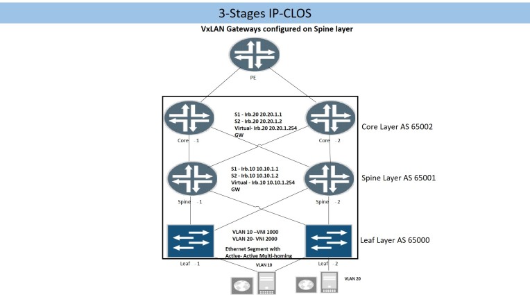
Figure (2.1)
Bare metal servers, hypervisor based server or network devices are connected to leaf layer. Layer 3 gateway for each VLAN/VNI will be configured at spine layer thus servers (on different VLANs) connected either on same or different leaf node will be 3 hops away from each other.
3.2 5-Stages IP CLOS
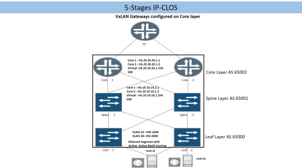
Fabric layer is added above spine layer to provide Inter-POD or Inter-Data Center connectivity. Layer 3 gateways for each VLAN/VNI will be configured on fabric layer thus 5 hops will be involved for inter-server communication (on different VLAN/VNI).
3.3 Collapsed IP CLOS
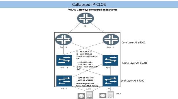
Physical connectivity for collapsed IP-CLOS is like 3-Stages or 5-stages IP-CLOS, however major difference is placement of layer 3 gateways for each VLAN/ VNI which will be on leaf layer.
- In all IP-CLOS solution; Intra-VLAN / VNI communication between two servers connected to same leaf node will be done on same leaf node.
- In 3-Stages or 5-Stages Inter-VLAN/ Inter-VNI communication will happen on Spine or Fabric layer sequentially.
- In collapsed IP-Fabric Solution Inter-VLAN/ Inter-VNI communication between 2 servers connected on same leaf node will happen on same leaf node.
4 Underlay Configuration
As explained above, sole purpose of underlay network is to provide IP connectivity between Spine and Leaf nodes and to re-distribute leaf/spine nodes loopback IP addresses to each other. The loopback reachability will be used to form overlay networks. EBGP is best suited to build underlay networks, IP-CLOS type (3-Stage, 5-Stage or Collapsed IP-Fabrics) does not have significant impact on EBGP design consideration but AS numbering has significant impact on underlay configuration.
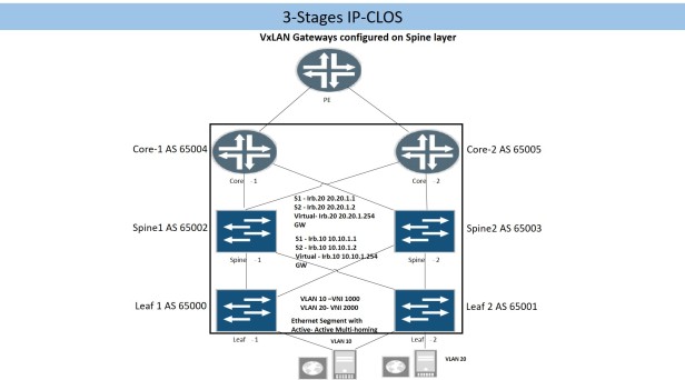
4.1 Different AS Number for Each Device
1st option is to use different AS number for each device at all layer. This is simplest option in terms of configuration requirement but bit difficult to maintain a pool of AS numbers specially if quantity of devices is large. Configuration will be same for 3-Stage, 5-Stage or Collapsed IP Fabric if each device at each layer uses different AS number.
4.1.1 Spine Configuration
protocols {
bgp {
group underlay {
export underlay;
local-as 65002;
multipath multiple-as;
neighbor 192.168.0.1 {
peer-as 65000;
description to-Leaf2;
}
neighbor 192.168.0.5 {
peer-as 65001;
description to-Leaf2;
}
}
}
}
Local-as knob allows us to use multiple autonomous system number, multipath multiple-as allows EBGP to select multiple routes and install in routing table for a NLRI.
4.1.2 Leaf Configuration
Below configuration snippet represent Leaf-1 underlay configuration and same configuration will be used by all remaining leaf devices, off-course on each leaf node local-as number will be changed accordingly.
protocols {
bgp {
group underlay {
export underlay;
local-as 65000;
multipath multiple-as;
neighbor 192.168.0.0 {
peer-as 65002;
description to-Spine1;
}
neighbor 192.168.0.2 {
peer-as 65003;
description to-Spine2;
}
}
4.2 Same AS Number at Same Layer
- Points to be considered at Leaf/ Core layer. Hence leaf/ core layers have same AS number so routes received on any leaf from other leaf nodes through spines will not be installed as active route because leaf node will find its own AS number in Network Layer Reachability Information (NLRI). So we need to add configuration knob local-as “loop” to avoid this scenario.
- Points to be considered at Spine layer. Spine devices will receive a NLRI from a leaf / core nodes and it will not re-advertise those NLRI to other leaf/ core nodes because of BGP rule that a NLRI will not be re-advertised to EBGP peer if it contains an AS number which matches the receiving node AS number. To avoid this effect, we need to configure advertise peer-as knob at spine layer under EBGP configuration.
4.2.1 Spine Configuration
protocols {
bgp {
group to-Leaf {
advertise-peer-as;
export underlay;
local-as 65001;
multipath;
neighbor 192.168.0.1 {
peer-as 65000;
description to-Leaf1;
}
neighbor 192.168.0.5 {
peer-as 65000;
description to-Leaf2;
}
}
group to-Core {
advertise-peer-as;
export underlay;
local-as 65001;
multipath;
neighbor 192.168.0.9 {
peer-as 65002;
description to-Core-1;
}
neighbor 192.168.0.11 {
peer-as 65002;
description to-Core-2;
}
}
}
}
4.2.2 Leaf Configuration
protocols {
bgp {
group underlay {
export underlay;
local-as 65000 loops 2;
multipath;
neighbor 192.168.0.0 {
description to-Spine-1;
peer-as 65001;
}
neighbor 192.168.0.2 {
description to-Spine-2;
peer-as 65001;
}
}
}
4.2.3 Core Layer Configuration
protocols {
bgp {
group underlay {
export underlay;
local-as 65002 loops 2;
multipath;
neighbor 192.168.0.8 {
description to-Spine1;
peer-as 65001;
}
neighbor 192.168.0.12 {
description to-Spine2;
peer-as 65001;
}
}
}
}
5 Common Configuration for Underlay
5.1 Loopback Re-Distribution into EBGP
policy-options {
policy-statement underlay {
term 1 {
from {
protocol direct;
route-filter 0.0.0.0/0 prefix-length-range /32-/32;
}
then accept;
}
}
}
5.2 Load balancing Policy
Configuring a load balancing policy and applying it as export policy to the forwarding-table will enable forwarding table to install all active next-hops for a NLRI and load balance egress traffic.
policy-options {
policy-statement lb {
then {
load-balance per-packet;
}
}
routing-options {
forwarding-table {
export lb;
}
}
6 Overlay Configuration
6.1 iBGP and Route Reflector Design
As per iBGP best design practices, 2 Spine devices will be configured as Route Reflector and leaf nodes will be configured as Route Reflector clients. EVPN signaling is mandatory to enable transportation of EVPN routes through control plane.
6.1.1 Spine MP-iBGP
routing-options {
autonomous-system 10;
}
protocols {
bgp {
group overlay {
type internal;
local-address 172.172.100.1;
family evpn {
signaling;
}
multipath;
cluster 0.0.0.1;
neighbor 172.172.1.1;
neighbor 172.172.2.1;
}
}
}
Global configuration of AS value will be used for overlay “MP-iBGP”
6.1.2 Leaf MP-iBGP
routing-options {
autonomous-system 10;
}
protocols {
bgp {
group overlay {
type internal;
family evpn {
signaling;
}
multipath;
neighbor 172.172.100.1;
neighbor 172.172.200.1;
}
}
7 L2-VTEP Configuration
7.1 VLAN to VxLAN Conversion
vlans {
vlan-10 {
vlan-id 10;
vxlan {
vni 1000;
ingress-node-replication;
}
}
vlan-20 {
vlan-id 20;
vxlan {
vni 2000;
ingress-node-replication;
}
}
}
VNI should be unique in VxLAN domain, ingress-node-replication defines how to handle BUM traffic.
7.2 Server Access Port
xe-0/0/2 {
esi {
00:11:22:33:44:55:aa:bb:cc:dd;
all-active;
}
unit 0 {
family ethernet-switching {
interface-mode trunk;
vlan {
members 10;
}
}
}
}
xe-0/0/3 {
unit 0 {
family ethernet-switching {
interface-mode trunk;
vlan {
members 20;
}
}
}
}
ESI value defines an Ethernet segment, as it enables an end device/server for active active multi-homing with with multiple leaf nodes. ESI value causes implicit configuration of esi-export/ esi-import policy for advertisement and acceptance of EVPN type 4 routes while using ESI value as BGP extended community.
7.3 EVPN Protocols and Virtual Switch
Under protocols evpn configuration hierarchy, VxLAN encapsulation, VNI values for each VxLAN and VNI specific router target communities are defined. Route target communities will be discussed in detail in later section.
protocols {
evpn {
encapsulation vxlan;
extended-vni-list [ 1000 2000 ];
multicast-mode ingress-replication;
vni-options {
vni 1000 {
vrf-target export target:10:1000;
}
vni 2000 {
vrf-target export target:10:2000;
}
}
}
}
Under switch-options configuration hierarchy VTEP source interface is defined which is always lo0.0. Besides VTEP source interface route-distinguisher is also defined which will uniquely defines the EVPN routes. VRF-import and vrf-target statement will be discussed in detail in later section. In QFX 5110 and 10K series we don’t have option to define multiple virtual switches but in Juniper MX Series router we can define multiple virtual-switches (which helps to maintain multi-tenancy)
switch-options {
vtep-source-interface lo0.0;
route-distinguisher 172.172.2.1:10;
vrf-import evpn-import;
vrf-target target:10:1;
}
8 Route Target Community
When EVPN routes are advertised through control plane, BGP extended route target community is attached to each VNI routes. Receiving VTEPs will match its vrf-target community with all EVPN routes received from remote peer and will accept and install only those route into bgp.evnp.0 routing table whose BGP extended route target community matches its own BGP extended target community.
8.1 Single Route-Target Policy for All VNIs
protocols {
evpn {
encapsulation vxlan;
extended-vni-list [1000 2000];
multicast-mode ingress-replication;
}
switch-options {
vtep-source-interface lo0.0;
route-distinguisher 172.172.1.1:10;
vrf-target target:10:1;
}
Vrf-target statement will add implicit export & import policy which will further add BGP extended community to all out going EVPN routes (except type 4). It will also import all incoming routes into bgp.evpn.0 routing table which matches the BGP extended community value. This method has serious implication on scalability, e.g if any leaf node is not interested in a specific VNI routes even then it will receive all EVPN routes for wanted and unwanted VNIs due to vrf-target statement.
8.2 Per VNI Route Target Policy
Vrf-target statement is defined per VNI, which will cause advertisement of unique BGP extended community per VNI.
protocols {
evpn {
encapsulation vxlan;
extended-vni-list [ 1000 2000 ];
multicast-mode ingress-replication;
vni-options {
vni 1000 {
vrf-target export target:10:1000;
}
vni 2000 {
vrf-target export target:10:2000;
}
}
}
}
Above configuration snippet will only add BGP extended community with type and 2 type 3 routes, for type 1 routes we still need to add vrf-target statement under switch-option configuration hierarchy. There is also explicit need to configure vrf-import policy which should accept all required VNI vrf-target values. The usage of import statement allows us to control manually what all VNI routes can imported into a specific leaf node.
switch-options {
vtep-source-interface lo0.0;
route-distinguisher 172.172.2.1:10;
vrf-import evpn-import;
vrf-target target:10:1;
}
policy-options {
policy-statement evpn-import {
term 1 {
from community vni-1000;
then accept;
}
term 2 {
from community vni-2000;
then accept;
}
term 3 {
from community type-1;
then accept;
}
}
community type-1 members target:10:1;
community vni-1000 members target:10:1000;
community vni-1000 members target:10:2000;
}
8.3 Auto VRF-Target Policy Generation
There is another point of consideration, if thousands of VNIs needs to be configured then configuration of per-vni vrf-target export/ import polices will be a cumbersome task and it can be avoided by generating auto vrf-target. Type 1 routes still need explicit export and import vrf-target polices.
protocols {
evpn {
encapsulation vxlan;
extended-vni-list all;
multicast-mode ingress-replication;
}
}
policy-options {
policy-statement evpn-import {
term 1 {
from community type-1;
then accept;
}
}
community type-1 members target:10:1;
}
switch-options {
vtep-source-interface lo0.0;
route-distinguisher 172.172.1.1:10;
vrf-import evpn-import;
vrf-target
{
target:10:1;
auto;
}
}
9 L3- VTEP Configuration
Inter-VxLAN communication required L3 gateway for each VxLAN and dependent on hardware. Following Juniper product line support inter-VxLAN communication: –
- Juniper QFX 5110 switches equipped with Broadcom Trident II Plus chipset
- Juniper QFX 10K series switches equipped with Juniper Q5 Chipset
- EX 9200 Series switches equipped with Juniper One chipset
- MX Series Router equipped with Juniper Trio Chipset
9.1 Collapsed IP CLOS
QFX 10K and QFX 5110 series switches are ideal for Leaf layer and support inter-VxLAN communication. One important consideration for configuration of L3 gateway is to maintain ARP Entries for gateway inside a virtual machine even if in VM moves its location. 2 methods are available to achieve this goal: –
- Configure same IP address and MAC address for specific IRB (integrated routing and bridging) interface on each Leaf.
- Configure “virtual-gateway” statement under IRB interface hierarchy and define the same IP address. Virtual gateway statement will enable all devices to use same mac address and leaf device configured with virtual-gateway will synch with each other (MAC and gateway IP address) through EVPN control plane.
Both methods have their pros and cons, “virtual-gateway” statements defiantly give us ease of configuration as we don’t have to manually configure MAC address on each leaf device. However, there is limitation on how many number of leaf devices can be configured with virtual-gateway statement (max 64) and it involves additional overhead in EVPN control plane for synchronization of virtual-gateways MAC and IP addresses.
vlans {
vlan-10 {
vlan-id 10;
l3-interface irb.10;
vxlan {
vni 1000;
}
}
vlan-20 {
vlan-id 20;
l3-interface irb.20;
vxlan {
vni 2000;
}
}
}
Interfaces {
irb {
unit 10 {
family inet {
address 10.10.1.1/24 {
virtual-gateway-address 10.10.1.254;
}
}
}
unit 20 {
family inet {
address 20.20.1.1/24 {
virtual-gateway-address 20.20.1.254;
}
}
}
}
}
2nd option is to use same MAC address for specific IRB interface on all leaf device
Interfaces {
irb {
unit 10 {
family inet {
address 10.10.1.1/24;
}
mac 00:00:44:00:55:10;
}
unit 20 {
family inet {
address 20.20.1.1/24;
}
mac 00:00:44:00:55:20;
}
}
}
With static MAC configuration option, MAC/IP address synchronization through EVPN control plane is not required among leaf devices. In this case, we need to configure additional knob under protocols evpn configuration hierarchy “default-gateway do-not-advertise”.
9.2 “3-Stage IP-CLOS”
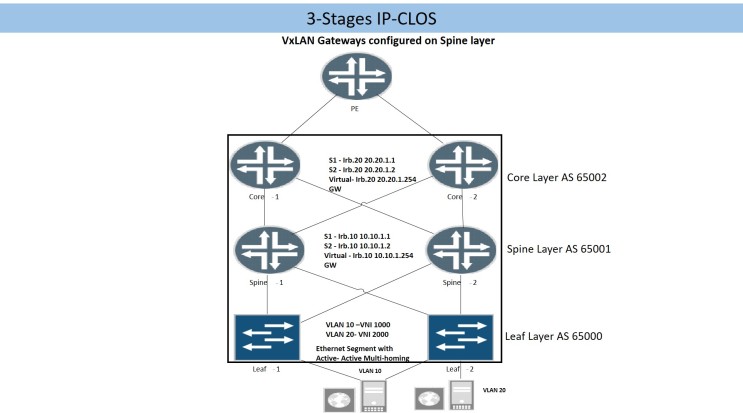
In 3-Stage IP-CLOS , L3 gateways are configured on spine devices, QFX 10K series switches or MX series routers are ideal boxes for spine layer. As discussed earlier we have options either to configure same static MAC entry with IRB interfaces on each spine device or to use virtual-gateway-address statement.
Below configuration snippet is taken from a MX series (version 16.1R3), we can create multiple virtual-switches in MX series router as compare to QFX series switches where we cannot create multiple virtual-switches.
routing-instances {
tenat1-sw {
vtep-source-interface lo0.0;
instance-type virtual-switch;
route-distinguisher 172.172.100.1:1;
vrf-import evpn-import;
vrf-target target:1:10;
protocols {
evpn {
encapsulation vxlan;
extended-vni-list [ 1000 2000 ];
multicast-mode ingress-replication;
}
}
bridge-domains {
BD-10 {
vlan-id 10;
routing-interface irb.10;
vxlan {
vni 1000;
ingress-node-replication;
}
}
BD-20 {
vlan-id 20;
routing-interface irb.20;
vxlan {
vni 2000;
ingress-node-replication;
}
}
}
}
}
policy-options {
policy-statement evpn-import {
term 1 {
from community type-1;
then accept;
}
term 2 {
from community vni-1000;
then accept;
}
term 3 {
from community vni-2000;
then accept;
}
}
community type-1 members target:1:10;
community vni-1000 members target:10:1000;
community vni-2000 members target:10:2000;
}
9.3 “5-Stages IP-CLOS”
Overlay network (MP-BGP) for “5-Stages IP-CLOS needs deliberate considerations: –
- Gateway for each VxLAN will be configured at Core/ Fabric layer.
- Leaf devices need MP-iBGP neighbor ship (family evpn signaling enabled) with core layer.
- 2 or more spine devices can be configured as router reflector for scalability.
- Core/Fabric device needs MP-iBGP neighbor ship with leaf devices.
- Keeping in view the scalability; it is recommended that Core/Fabric devices should also be configured as route reflector client so that single MP-iBGP overlay network will be established between leaf, spine and core/fabric layer.
9.3.1 Leaf Layer Configuration
Leaf node configuration will be same as described in one of above section “L2-VTEP Configuration”
9.3.2 Spine Layer Configuration
protocols {
bgp {
group overlay {
type internal;
local-address 172.172.100.1;
family evpn {
signaling;
}
cluster 0.0.0.1;
multipath;
neighbor 172.172.1.1 {
description Leaf-1;
}
neighbor 172.172.2.1 {
description Leaf-2;
}
neighbor 172.172.0.1 {
description Core-1;
}
neighbor 172.172.0.2 {
description Core-2;
}
}
}
9.3.3 Core Layer
routing-options {
autonomous-system 10;
}
protocols {
bgp {
group overlay {
type internal;
local-address 172.172.0.1;
family evpn {
signaling;
}
multipath;
neighbor 172.172.100.1 {
description Spine-1;
}
neighbor 172.172.200.1 {
description Spine-2;
}
}
}
}
routing-instances {
tenat1-sw {
vtep-source-interface lo0.0;
instance-type virtual-switch;
route-distinguisher 172.172.100.1:1;
vrf-import evpn-import;
vrf-target target:1:10;
protocols {
evpn {
encapsulation vxlan;
extended-vni-list [ 1000 2000 ];
multicast-mode ingress-replication;
}
}
bridge-domains {
BD-10 {
vlan-id 10;
routing-interface irb.10;
vxlan {
vni 1000;
ingress-node-replication;
}
}
BD-20 {
vlan-id 20;
routing-interface irb.20;
vxlan {
vni 2000;
ingress-node-replication;
}
}
}
}
policy-options {
policy-statement evpn-import {
term 1 {
from community type-1;
then accept;
}
term 2 {
from community vni-1000;
then accept;
}
term 3 {
from community vni-2000;
then accept;
}
}
community type-1 members target:1:10;
community vni-1000 members target:10:1000;
community vni-2000 members target:10:2000;
}
10 Conclusion
IP-CLOS with EVPN-VxLAN defiantly offers solution for next generation data center however it needs lot of deliberate considerations for proper design, configuration and operation & maintenance of IP-CLOS based data center. Underlay and overlay BGP and L3 VTEP configuration are major factors which differentiate among various IP-CLOS design options.

Hi blogger, do you monetize your blog ? There is easy
method to earn extra money every month, just search on youtube – How to earn with wordai 4
LikeLike