")
In my earlier blog (Junos High Availability Design Guide) it was discussed how to make use of redundant routing engines by configuring features like (GRES, NSR, NSB) for reduction of downtime to minimum possible level.
The real problem is that one RE is active at one time and all PFEs must be connected with active RE . In case of failure of primary Routing Engine (RE) the backup RE will take over and all PFEs now, needs to connect to new primary RE. This scenario can cause momentary disruption of services.
MC-LAG (Active-Active) is correct solution to above described problem as it offers 2 active REs in 2 different devices/ chassis. Important concepts for MC-LAG proper configuration / functionality are as under:-
- Inter Chassis Control Protocol. The MC-LAG peers use the Inter-Chassis Control Protocol (ICCP) to exchange control information and coordinate with each other to ensure that data traffic is forwarded properly. ICCP replicates control traffic and forwarding states across the MC-LAG peers and communicates the operational state of the MC-LAG members. It uses TCP as a transport protocol and requires Bidirectional Forwarding Detection (BFD) for fast convergence. Because ICCP uses TCP/IP to communicate between the peers, the two peers must be connected to each other. ICCP messages exchange MC-LAG configuration parameters and ensure that both peers use the correct LACP parameters. ICCP configuration parameters as under:-
- Local-IP-Address– IP adress configured on lcoal MC-LAG member that will be used to estblish ICCP session with MC-LAG peer device. (lo0 address is recommended to be used for ICCP peer establishment)
- ICCP Peer- IP adress configured on peer MC-LAG member that will be used to estblish ICCP session with local MC-LAG device.(lo0 address is recommended to be used for ICCP peer establishment)
- session-establishment-hold-time- 50 seconds is recommended vlaue for faster ICCP connection establishment among MC-LAG peers
- redundancy-group-id-list- it must be same on both MC-LAG peers and will be used in MC-ae configuration
- liveness-detection minimum-interval. BFD session timer to detect failure of MC-LAG peer ( 60 ms is used in this topology)
- liveness-detection multiplier. This multiplier will be used along with liveness-detection minimum-interval to detect failure if ICCP peer , default value is 3. So for this topology BFD failure detection will be 60×3 =180 ms)
- Inter Chassis Link (ICL)– ICL is used to forward data traffic across the MC-LAG peers
- Multi Chassis Control Aggregated Link (MC-AE)- 1 x interface from each member of MC-LAG peer is connected to downstream or upstream network devices or compute machines. The devices connected to MC-LAG peers will not know that they are connected to different devices rather they will treat the link as normal Aggregate Link and continue to load balance traffic over LAG member interfaces.
- lacp system-id – Must be same configuration on both MC -LAG peer but must be unique in MC-LAG configuration from other MC-AE. Its LACP ID that will be transmitted to upward or downward connected devices from both MC-LAG peers and link from both MC-LAG peer who has same system-id will be considered as same LAG member.
- lacp admin-key – Must be same configuration on both MC -LAG peer but must be unique in MC-LAG configuration from other MC-AE interfaces.
- mc-ae-id- Must be same configuration on both MC -LAG peer but must be unique in MC-LAG configuration from other MC-AE interfaces
- mc-ae redundancy-group – Must be same configuration on both MC -LAG peer and it should be as per redundancy-group value configured under ICCP
- mc-ae chassis-id – Specify the chassis ID for Link Aggregation Control Protocol (LACP) to calculate the port number of MC-LAG physical member links.Values: 0 or 1
- mc-ae mode – Active-Active is used in this topology and it will ensure both MC-LAG peers are actively sending and transmitting data despite the fact that VRRP is master in only 1 MC-LAG peer.
- mc-ae status-control (Active / standby)- Desctibe the status of MC-AE interface when ICL goes down. It must be active in 1 MC-LAG peer and stadby in other peer.
- prefer-status-control-active– Specify that the node configured as status control active become the active node if the peer of this node goes down
- Multi-chassis-protection. If the Inter-chassis Control Protocol (ICCP) connection is up and the inter-chassis link (ICL) comes up, the peer configured as standby brings up the multi chassis aggregated Ethernet interfaces shared with the peer. Multi chassis protection must be configured on one interface for each peer.
- Hold Time Configure a hold-down timer on the ICL member links that is greater than the configured BFD timer for the ICCP interface. This prevents the ICL from being advertised as being down before the ICCP link is down. If the ICL goes down before the ICCP link, this causes a flap of the MC-LAG interface on the status-control standby node, which leads to a delay in convergence
- Service-id. The switch service ID is used to synchronize applications, IGMP, ARP, and MAC learning across MC-LAG members
- arp-l2-validate. Enables periodic checking of ARP Layer 3 addressing and MAC Layer 2 addressing tables, and fixes entries if they become out of sync among MC-LAG peers.
Note:- On EX9200 switches, the prefer-status-control-active statement with the mc-ae status-control standby configuration is required to prevent the LACP MC-LAG system ID from reverting to the default Link Aggregation Control Protocol (LACP) system ID on ICCP failure.
The hold-time down value (at the [edit interfaces interface-name] hierarchy level) for the ICL with the mc-ae status-control standby configuration must be higher than the ICCP Bidirectional Forwarding Detection (BFD) timeout. This configuration prevents data traffic loss by ensuring that when the router or switch with the mc-ae status-control active configuration goes down, the router or switch with the mc-ae status-control standby configuration does not go into standby mode.
.
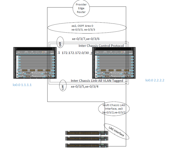
Topology Description
- In above topology 2 x EX 9208 are deployed as Campus Core Router/ Switch.
- ae0 is configured as ICL-PL and ae1 is configured as ICL between MC-LAG pair.
- Access Layer devices (which is EX 4300 VC) is connected on ae3 on MC-LAG pair (through normal LAG at access side and MC-AE on MC-LAG pair).
- Upward devices is service provider router and connected on ae2 on MC-LAg Pair.
- VRRP over IRB (integrated routing and bridge interface, IRB is same like RVI old Junos EX folks or SVI for Cisco folks) will be configured so that downstream Access devices can have single gateway on MC-LAG pair.
- OSPF will be configured between Campus Core Router (i.e MC-LAG pair) and service provider router. The service provider router will view the MC-LAG pair as 2 different next hops and will have 2 OSPF neighbors (1 with each MC-LAG member device)
Note: VRRP over IRB will be configured in order to provide single gateway on MC-LAG pair to access layer devices. The normal behavior for VRRP is that only VRRP master will active and backup will be ready to take in case of master fails but in Active-Active MC-LAG scenarios both members of VRRP will transmit and receive data.
Lets starts with step by step configuration and explanation
ICL-PL Link configuration
set chassis aggregated-devices ethernet device count 3 #create 4 x ae on both MC LAG pair
#ICCP-link configuration
set interfaces ae0 description ICCP-PL # EX-9208-1
set interfaces ae0 aggregated-ether-options lacp active
set interfaces ae0 aggregated-ether-options lacp periodic fast
set interfaces ae0 unit 0 family inet address 172.172.172.1/30
set interfaces xe-0/3/6 ether-options 802.3ad ae0
set interfaces xe-0/3/7 ether-options 802.3ad ae0
set interfaces lo0 unit 0 family inet address 1.1.1.1/32
set interfaces ae0 description ICCP-PL # EX-9208-2
set interfaces ae0 aggregated-ether-options lacp active
set interfaces ae0 aggregated-ether-options lacp periodic fast
set interfaces ae0 unit 0 family inet address 172.172.172.1/30
set interfaces xe-0/3/6 ether-options 802.3ad ae0
set interfaces xe-0/3/7 ether-options 802.3ad ae0
set interfaces lo0 unit 0 family inet address 2.2.2.2/32
#Configure OSPF on ae0 and lo0.0 on both MC-LAG members , later lo0 addresses of each member will be used for Inter-chassis Control Protocol (ICCP) configuration
set protocols ospf area 0.0.0.0 interface ae0.0 interface-type p2p
set protocols ospf area 0.0.0.0 interface lo0.0
# ICL Configuration
set interfaces xe-0/3/4 # EX-9208-1
set interfaces xe-0/3/4 ether-options 802.3ad ae1
set interfaces xe-0/3/5 ether-options 802.3ad ae1
set interfaces xe-0/3/4 hold-time up 0 # EX-9208-2 i.e mc-ae status-control standby
set interfaces xe-0/3/4 hold-time down 300
set interfaces xe-0/3/4 ether-options 802.3ad ae1
set interfaces xe-0/3/5 hold-time up 0
set interfaces xe-0/3/5 hold-time down 300
set interfaces xe-0/3/5 ether-options 802.3ad ae1
set interfaces ae1 description ICL-LINK # Same configration of both MC-LAG Peers
set interfaces ae1 aggregated-ether-options lacp active
set interfaces ae1 aggregated-ether-options lacp periodic fast
set interfaces ae1 unit 0 family ethernet-switching interface-mode trunk
set interfaces ae1 unit 0 family ethernet-switching vlan members all
# ICCP Configuration
set protocols iccp local-ip-addr 1.1.1.1 #EX-9208-1
set protocols iccp peer 2.2.2.2 session-establishment-hold-time 50
set protocols iccp peer 2.2.2.2 redundancy-group-id-list 1
set protocols iccp peer 2.2.2.2 liveness-detection minimum-interval 60
set protocols iccp peer 2.2.2.2 liveness-detection multiplier 3
set protocols iccp local-ip-addr 2.2.2.2 #EX-9208-2
set protocols iccp peer 1.1.1.1 session-establishment-hold-time 50
set protocols iccp peer 1.1.1.1 redundancy-group-id-list 1
set protocols iccp peer 1.1.1.1 liveness-detection minimum-interval 60
set protocols iccp peer 1.1.1.1 liveness-detection multiplier 3
# Multi-Chassis protection
set multi-chassis multi-chassis-protection 2.2.2.2 interface ae1 #EX-9208-1, ae1 is ICL
set multi-chassis multi-chassis-protection 1.1.1.1 interface ae1 #EX-9208-2, ae1 is ICL
# service-id
set switch-options service-id 1 # Must be same on both MC-LAG peers
# Periodic ARP synchronization
set interfaces irb arp-l2-validate # Must be same on both MC-LAG peers
MC-Ae interface (ae2 connected to Up link device i.e Service Provider Router)
set interfaces xe-0/3/3 ether-options 802.3ad ae2 #EX-9208-1
set interfaces ae2 description to-WAN
set interfaces ae2 aggregated-ether-options lacp active
set interfaces ae2 aggregated-ether-options lacp periodic fast
set interfaces ae2 aggregated-ether-options lacp system-id 00:00:00:00:00:02
set interfaces ae2 aggregated-ether-options lacp admin-key 2
set interfaces ae2 aggregated-ether-options mc-ae mc-ae-id 2
set interfaces ae2 aggregated-ether-options mc-ae redundancy-group 1
set interfaces ae2 aggregated-ether-options mc-ae chassis-id 0
set interfaces ae2 aggregated-ether-options mc-ae mode active-active
set interfaces ae2 aggregated-ether-options mc-ae status-control active
set interfaces ae2 unit 0 family ethernet-switching interface-mode access
set interfaces ae2 unit 0 family ethernet-switching vlan members WAN
set interfaces xe-0/3/3 ether-options 802.3ad ae2 #EX-9208-2
set interfaces ae2 description to-WAN
set interfaces ae2 aggregated-ether-options lacp active
set interfaces ae2 aggregated-ether-options lacp periodic fast
set interfaces ae2 aggregated-ether-options lacp system-id 00:00:00:00:00:02
set interfaces ae2 aggregated-ether-options lacp admin-key 2
set interfaces ae2 aggregated-ether-options mc-ae mc-ae-id 2
set interfaces ae2 aggregated-ether-options mc-ae redundancy-group 1
set interfaces ae2 aggregated-ether-options mc-ae chassis-id 1
set interfaces ae2 aggregated-ether-options mc-ae mode active-active
set interfaces ae2 aggregated-ether-options mc-ae status-control standby
set interfaces ae2 aggregated-ether-options mc-ae events iccp-peer-down prefer-status-control-active
set interfaces ae2 unit 0 family ethernet-switching interface-mode access
set interfaces ae2 unit 0 family ethernet-switching vlan members WAN
MC-Ae interface (ae3 connected to down link device i.e EX 4300 Virtual Chassis)
set interfaces xe-0/3/2 ether-options 802.3ad ae2 #EX-9208-1
set interfaces ae3 description to-ACCESS-Device
set interfaces ae3 aggregated-ether-options lacp active
set interfaces ae3 aggregated-ether-options lacp periodic fast
set interfaces ae3 aggregated-ether-options lacp system-id 00:00:00:00:00:03
set interfaces ae3 aggregated-ether-options lacp admin-key 3
set interfaces ae3 aggregated-ether-options mc-ae mc-ae-id 3
set interfaces ae3 aggregated-ether-options mc-ae redundancy-group 1
set interfaces ae3 aggregated-ether-options mc-ae chassis-id 0
set interfaces ae3 aggregated-ether-options mc-ae mode active-active
set interfaces ae3 aggregated-ether-options mc-ae status-control active
set interfaces ae3 unit 0 family ethernet-switching interface-mode access
set interfaces ae3 unit 0 family ethernet-switching vlan members DATA
set interfaces xe-0/3/2 ether-options 802.3ad ae2 #EX-9208-2
set interfaces ae3 description to-ACCESS-Device
set interfaces ae3 aggregated-ether-options lacp active
set interfaces ae3 aggregated-ether-options lacp periodic fast
set interfaces ae3 aggregated-ether-options lacp system-id 00:00:00:00:00:03
set interfaces ae3 aggregated-ether-options lacp admin-key 3
set interfaces ae3 aggregated-ether-options mc-ae mc-ae-id 3
set interfaces ae3 aggregated-ether-options mc-ae redundancy-group 1
set interfaces ae3 aggregated-ether-options mc-ae chassis-id 1
set interfaces ae3 aggregated-ether-options mc-ae mode active-active
set interfaces ae3 aggregated-ether-options mc-ae status-control active
set interfaces ae2 aggregated-ether-options mc-ae events iccp-peer-down prefer-status-control-active
set interfaces ae3 unit 0 family ethernet-switching interface-mode access
set interfaces ae3 unit 0 family ethernet-switching vlan members DATA
# VRRP and IRB Configuration
set interfaces irb unit 160 family inet address 10.102.160.2/29 arp 10.102.160.3 l2-interface ae1.0 # irb.160 will be used on EX 9208-1 to establish OSPF peer ship with uplink router
#static ARP entry for MC-LAG peer is required for VRRP over IRB configuration , ae1 is ICL
set interfaces irb unit 160 family inet address 10.102.160.2/29 arp 10.102.160.3 mac cc:e1:7f:a7:43:f0
#mac address of IRB interface from other MC-LAG peer and can be obtained by operation mode command “show interface irb” once ICCP session is established.
set interfaces irb unit 160 family inet address 10.102.160.2/29 vrrp-group 160 virtual-address 10.102.160.1
set interfaces irb unit 160 family inet address 10.102.160.2/29 vrrp-group 160 priority 254 #VRRP master
set interfaces irb unit 160 family inet address 10.102.160.2/29 vrrp-group 160 accept-data
set interfaces irb unit 160 family inet address 10.102.160.3/29 arp 10.102.160.2 l2-interface ae1.0 #irb.160 will be used on EX 9208-2 to establish OSPF peer ship with uplink router
#static ARP entry for MC-LAG peer is required for VRRP over IRB configuration , ae1 is ICL
set interfaces irb unit 160 family inet address 10.102.160.3/29 arp 10.102.160.2 mac cc:e1:7f:a7:3f:f0
#mac address of IRB interface from other MC-LAG peer and can be obtained by operation mode command “show interface irb” once ICCP session is established.
set interfaces irb unit 160 family inet address 10.102.160.3/29 vrrp-group 160 virtual-address 10.102.160.1
set interfaces irb unit 160 family inet address 10.102.160.3/29 vrrp-group 160 priority 100 #VRRP backup
set interfaces irb unit 160 family inet address 10.102.160.3/29 vrrp-group 160 accept-data
set interfaces irb unit 50 family inet address 10.102.50.2/23 arp 10.102.50.3 l2-interface ae1.0 #irb.50 will be used on EX 9208-1 as gateway for traffic coming from access devices
#static ARP entry for MC-LAG peer is required for VRRP over IRB configuration , ae1 is ICL
set interfaces irb unit 50 family inet address 10.102.50.2/23 arp 10.102.50.3 mac cc:e1:7f:a7:43:f0
#mac address of IRB interface from other MC-LAG peer and can be obtained by operation mode command “show interface irb” once ICCP session is established.
set interfaces irb unit 50 family inet address 10.102.50.2/23 vrrp-group 50 virtual-address 10.102.50.1
set interfaces irb unit 50 family inet address 10.102.50.2/23 vrrp-group 50 priority 254 #VRRP mater
set interfaces irb unit 50 family inet address 10.102.50.2/23 vrrp-group 50 accept-data
set interfaces irb unit 50 family inet address 10.102.50.3/23 arp 10.102.50.2 l2-interface ae1.0 #irb.50 will be used on EX 9208-2 as gateway for traffic coming from access devices
#static ARP entry for MC-LAG peer is required for VRRP over IRB configuration , ae1 is ICL
set interfaces irb unit 50 family inet address 10.102.50.3/23 arp 10.102.50.2 mac cc:e1:7f:a7:3f:f0
#mac address of IRB interface from other MC-LAG peer and can be obtained by operation mode command “show interface irb” once ICCP session is established
set interfaces irb unit 50 family inet address 10.102.50.3/23 vrrp-group 50 virtual-address 10.102.50.1
#VLAN Configuration
set vlans DATA vlan-id 50 l3-ineerface irb.50
set vlans WAN vlan-id 160 l3-ineerface irb.160
#OSPF Configuration in MC-LAG Peers for uplink router
set protocols ospf area 0.0.0.0 interface irb.160
Both MC-LAG peer will establish OSPF neighbor-ship with Uplink router and with other MC-LAG peer.

Nice article….I have one question what could be advatage or diffrence between MC LAG and Virtual chassis than ?
Many THanks,
Brijesh PAtel
LikeLike
Thanks Brijesh Patel, Virtual Chassis is Juniper propriety where as MC-LAG is industry standard. In MC-LAG we have 2 active control planes whereas in VC we have only 1 active control plane at single time. MC-LAG is ideal in certain deployments scenarios e.g one I mentioned in my blog. VC is working perfectly fine on Juniper devices based on merchant chip-set (Broad-com). The devices which are coming with Juniper customized chip-set ( EX 9200 has Juniper One Chip-set , MX series routers has Juniper Trio Chip , QFX 10k has Q5 Chip-set) may not be stable/ supporting VC configuration (at least I tested in EX 9200 VC is not stable) . But check Juniper tech Publication for feature set support and PR search for any feature set instability (if reported)
LikeLike
Thanks for prompt response…Control plane is ideal difference
LikeLike
Hi,
After i implement mclag active/active mode there is big differences output from one chassis to another, do you have any experience with it?
Thanks,
LikeLike
Great article – thanks. This article really helped me with configuration QFX5100 + MC-LAG + OSPF.
But I have 1 problem. You set static ARP, but there is still no MAC in the ethernet table and traffic.
When packet comes from PE router to peer2 over peer1, then peer1 treat this packet as unknown unicast.
LikeLike
why use layer 3? most other giudes are L2 on the iccp link
LikeLike
Do you have any espirientces with MC-LAG on ACX5448 ? I have issue on device connected to two ACX5448 boxes. When on master / main ACX port on MC-LAG goes down I don’t get any MACs from ACX with standby status-control.
LikeLike