
The objective of this blog is to discuss end to end packet (client to server) traversing through a service provider network with special consideration on performance effecting factors.
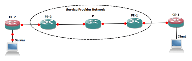
We will suppose client needs to access any of the service hosted in server connected with CE-2, all the network links and NICs on end system are Ethernet based. Almost all the vendors compute machines (PC/ servers) are generating IP data gram with 1500 bytes size (20 bytes header +1480 data bytes) in normal circumstances.
Fragmentation:- If any of link is unable to handle 1500 size IP data-gram then packet will be fragmented and forwarded to its destination where it will be re-assembled. The fragmentation and re-assembly will introduce overhead and defiantly over all performance will be degraded. In IP header following fields are important to detect fragmentation and to re-assemble the packets.
- Identification:- Is unique for all segments if packet is fragmented at all
- Flags – 3 bits . Bit 0 always 0, bit 1 -DF (Fermentation allowed or not 0 and 1 respectively), Bit 2-MF (More fragments expected or Last , 1 and 0 respectively)
- Fragments Offset :- Determine where data will start after removal of IP header in 1st and subsequent segments once packet is re-assembled.
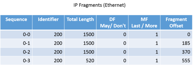
With below example we can understand transfer of IP data-gram between end system. Total size of IP data-gram is 4860 bytes which includes 20 bytes IP header so total data bytes are 4840.

As earlier explained Ethernet based NICs starts assume the default IP packet size 1500 bytes (20 bytes header + 1480 bytes data). So packets will be divided in 1480 bytes size chucks and will be transmitted after adding 20 bytes IP header.
The receiving host will reassemble the data once all fragments are received and will place the data bytes extracted from all fragments into relevant position inside original packet as it was before on sending host before fragmentation. Fragment offset value will be used for this purpose (its always multiplier of 8)
- 1st fragment data= 1480 bytes (0-1479)
- 2nd fragment data =1480 bytes (placement start at 1480 and end at 2959 bytes, fragment offset 185 x8 =1480)
- 3rd fragment data =1480 bytes (placement start at 2960 and end 4439 bytes, fragment offset 370 x8 =2960)
- 4th fragment data = 400 bytes (placement start at 4440 and end 4840 bytes, fragment offset 555 x8 =4440)
- Total data bytes are now 4840 and if we add 20 bytes IP header it will become 4860 bytes which was size of IP data-gram on sending host before fragmentation starts.
Everything handled smoothly and no performance degradation observed, end system uses 2 mechanisms for smooth data transfers:-
Path MTU Discovery -MTUD :– Path MTUD is defined in RFC 1191 where end systems detect maximum allowed MTU on a communication path. End system starts sending IP packets by using MTU of outing interface (default value is 1500 with 20 bytes IP header and 1480 data bytes) and DF bit SET. If any of link in between source and destination does not support 1500 bytes size IP packet then “ICMP destination un-reachable” with type 3, code 4 returned to originator host because of DF bit SET value as it tells “do not fragment this packet”. When such messages are initiated MTU of next hop is also included in it by the router which was unable to pass 1500 bytes IP packet. This process will continue until originator host finds maximum MTU allowed on a communication path till its destination and subsequently adjust its MTU for outgoing interface.
TCP Maxim Segment Size -MSS- RFC 2923:- TCP MSS size of TCP data in an IP packet (IP MTU-40) e.g 1500-40=1460 where 40 comes from 20 bytes IP header and 20 bytes TCP header. New TCP stack implies TCP MSS detection mechanism between end systems to identify maximum TCP segment can be allowed on opposite end system and thus adjust its sending TCP MSS accordingly.
Impact of Fragmentation:- End system can handle fragmentation without much overhead as they have sufficient resources (buffer to hold fragments until last packet arrives and CPU to re-assemble the packet in original order as it was on originator host before fragmentation). Routers can do the fragmentation fairly easily as all information required for fragmentation is available in original packet header and router just need to replicate the header and add fragment offset , MF flag and sequence no. But devices which handle packets from layer 4 and above then need to re-assemble the all fragments into original IP segment before any further processing such sort of devices may face performance issues with fragmentation and packet re-assembly.
As in our above example we suppose originator host start sending IP packet (1500 bytes) with DF bit value=1 (which means fragmentation not allowed). Now suppose, if a link between P and PE2 router has IP MTU of 1400 bytes and fragmentation is not allowed so packet will be dropped on P router and as subsequent action ICMP destination un-reachable with type 3, code 4″ will be returned to the originator host. If this message does not reach the originator host or unable to report MTU (as per RFC specification) of next-hop on the router where packet was dropped. Then only option available with application administrator is to clear the DF bit on originator host which mean if any links comes across with lesser MTU then packet can be fragmented.
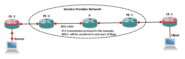
Now suppose IP packet with 1500 bytes and DF Bit=0 (fragmentation allowed) has been initiated from client, it reaches P routers and finds MTU of next-hop is 1400 which is lesser then original packet size. Hence DF bit is clear so P router will fragments the packet and transmit 1400 bytes (20 IP header and 1380 Data bytes) and then 120 bytes packet. Original packet which arrived at P router was of 1500 bytes size will be transmitted in 2 segments toward destination.
As in above referred example IP segment size was 4840 including 20 bytes IP head and it was transmitted in 4 segments by the originator ( 3x 1500 bytes segments and 1 segment with 520 segment (all fragments includes 20 bytes IP header). 1st three segments will be fragmented on P routers and will be transmitted in 2 segments of 1420 and 120 bytes . It looks normal with respect to forwarding operation on router but lets suppose any of 100 bytes segments transmitted by P router does not reach destination due to congestion on any link , in this case destination host will not be able to re-assemble the packet due to lost of 1 fragment. Thus whole transmission needs to be repeated and one can imagine the impacts on performance.
But usually Service Providers have Service Level Agreement (SLA) with corporate customers to support minimum MTU (usually it is 1500 bytes). In next blog we will discuss MTU overhead for various tunneling / VPN approaches (e.g L3PVN, L2VPN/VPLS , GRE & IPsec from CE-1 to CE-2)
