
In previous blog we discussed high level for Juniper Contrail Data Center Interconnect and how to connect physical servers with servers deployed inside SDN environment. In this blog we will have deep dive for both scenarios. We will discuss in detail configuration options , control plane and data plane operations involved in both options:-
Next blog: Contrail Integration with Bare Metal Devices via EVPN-VxLAN
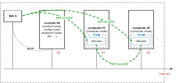
Following component are included in reference topology:-
- 1 x MX-5 will be configured as Data Center Edge Router
- Contrail Control Node
- Compute 51 (which has 1 x vRouter)
- Compute 52 (Which has 1 x vRouter)
- MP-iBGP will be configured by Contrail Control Node between itself and all vRouters.
- Contrail node will act as Route Reflector (RR) and all vRouter will act as client to RR.
- vRouter will establish GRE tunnel (for data plane forwarding) with all other vRouter .
- MX-5 (Data Center Edge Router) will also establish MP-iBGP peer-ship with Contrail Control node and will establish GRE tunnel with all vRouters and Contrail.
Now if we recall iBGP forwarding rules and co-relate to our environment:-
- All vRouter which are RR clients will transmit routes only to RR.
- RR will receive the routes from any of the client and will transmit received routes to all clients (except the vRouter from where the routes came) and to all non-client iBGP neighbor (which is MX-5 here)
- MX-5 will transmit routes to Contrail Control Node (RR) and these routes will be subsequently transmitted by RR to all clients.
- Full mesh of GRE tunnels will be established between MX-5 and all vRouters which will be used for forwarding plane.
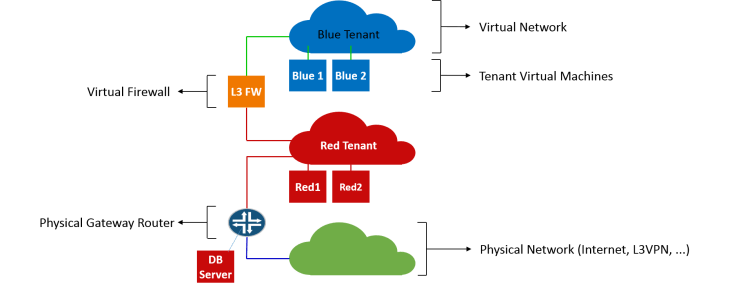
We have created 2 x tenants (Red and Blue) inside virtual Data Center. Red tenant VM also needs to talk with one DB Servers which is installed in physical compute machines.
- 1.1.1.0/24 subnet will be used for Red tenants VMs, route-target value 100:1.
- 2.2.2.0/24 subnet will be used for Blue tenant VMs, route-target value 200:1.
- IP address for physical Data base server which needs to communicate with Red tenant is 13.13.13.13.
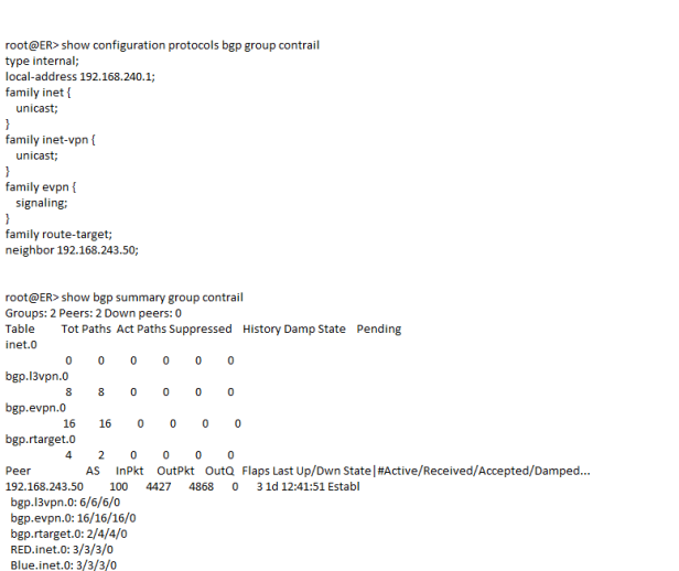
Above snippet shows BGP configuration on MX-5 and session state with Contrail Control Node. We can see many routing tables showing no of prefixes received and accepted.
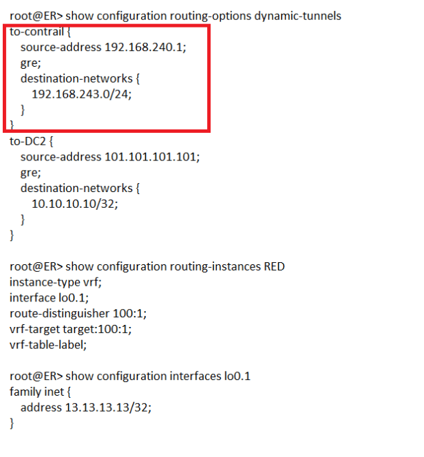
Above snippets show following:-
- Dynamic GRE tunnel configuration, in absence of MPLS LSPs inside Data Center GRE tunnels will be used to populate inet.3 routing table.
- RED routing instance configuration with route-target community (which must be matching with route-target community configured on Contrail Control Node for RED subnet).
- Interface lo0.1 is depicting here Data Base Sever. vrf-table-label causing auto-export of interface routes into BGP after adding route-target community. Without this statement we need to configure routing policy to re-distribute interface routes into BGP.
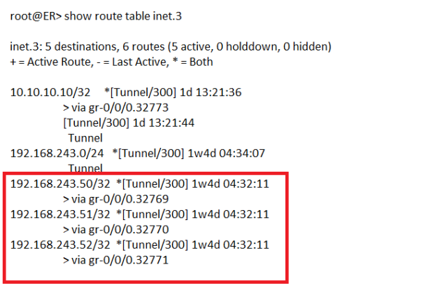
- inet.3 routing tables is showing address for Contrail Control and 2 x other compute nodes which means full mesh GRE tunnel has been established for data plane forwarding.
Now comes to actual routes received from Contrail Control Node for RED VPN:-
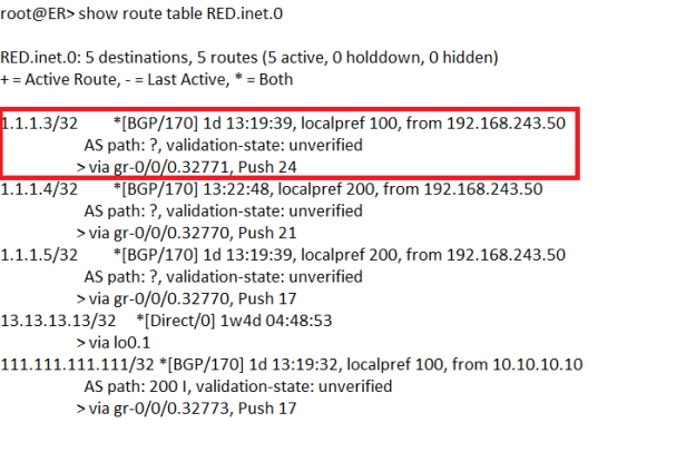
We can see 3 x routes has been received from 192.168.243.50 which is Contrail Control Node. Now lets see details of route 1.1.1.3/32:-
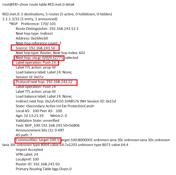
From above snippet following can be concluded:-
- Route 1.1.1.3/32 is learned from 192.168.243.50 (which is Contrail Control Node)
- Protocol Next-hop is 192.168.243.52 (which is compute 52 address) so it means RED VM with address 1.1.1.3/32 is located on 192.168.243.52 compute node.
- We can also see next hop interface is gr-0/0/0.32771 and with label operation Push (label value of 24).
- Route target community value is target:100:1 which depicts RED tenant.
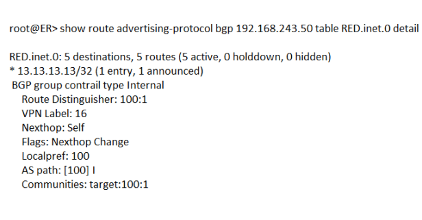
Above snippet is showing Data Base server route being advertised to Contrail Control Node with Route target community 100:1. Contrail Control Node will further re-advertise this route to vRouters on compute 51 and compute 52. On each vRouter route-target community will be checked and if it matches with any VRF then this route will be accepted and installed into that particular VRF.
Now consider a scenario where we need L2 & L3 Data Center Interconnect (DCI) for RED tenant.
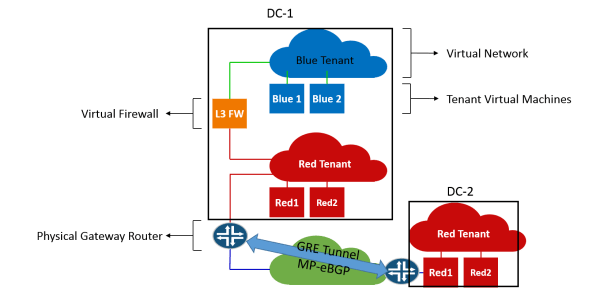
L3 DCI has never been a challenge and requirement can be meet through IP/VPN or through many other ways (IPSec , GRE etc). The real challenge lies in L2 DCI as traditionally enterprises are dependent either on Dark Fiber or L2 services (VPLS etc) from service provider. Hence both solution involves additional cost.
Now we will look how Ethernet VPN (EVPN) can helps us for L2 DCI and particularity I will focus, for EVPN we do not have dependency on service provider network (except layer 3 IP connect). We will configure GRE tunnel between Data Center Edge routers, once GRE tunnel is established we will configure MP-eBGP between both DCs (with family inet-vpn unicast and evpn signaling).
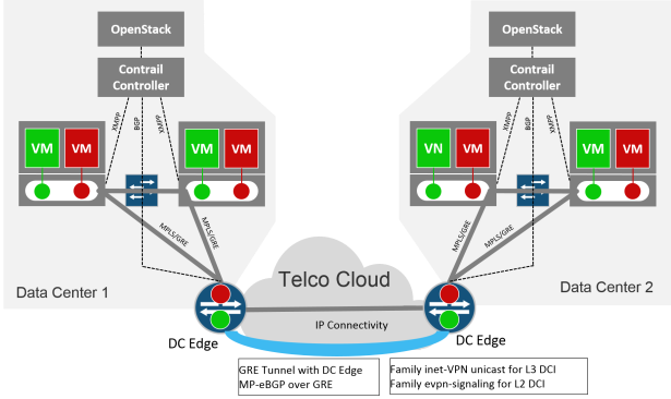
The simple piece of configuration will solve the big problem involved in L2 DCI and real support is MP-BGP (by simply adding evpn signaling) we achieved our target.
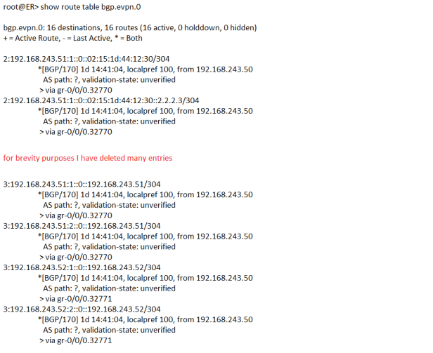
Above snippet shows bgp.evpn.0 routing table, now lets explore the entries:-
3:192.168.243.51:1::0::192.168.243.51/304 (3 : <RD> :: <VLAN-ID> :: <ROUTER-ID> /304)
1st digit in the prefix shows the type of EVPN route, type 3 is Inclusive multicast Ethernet tag route, it depicts multicast tunnel over which un-unknown uni-cast traffic will be forwarded to this particular vRouter (compute machine). 192.168.243.51 depicts compute node 51 and :1 shows one of the 2 VRF which are created on compute 51 (RED or BLUE). Let’s see more detail about this route to discover other information.
3:192.168.243.51:1::0::192.168.243.51/304 (1 entry, 1 announced)
*BGP Preference: 170/-101
Route Distinguisher: 192.168.243.51:1
PMSI: Flags 0x80: Label 16: Type INGRESS-REPLICATION 192.168.243.51
Next hop type: Indirect
Address: 0x26ffb74
Next-hop reference count: 8
Source: 192.168.243.50
Protocol next hop: 192.168.243.51
Indirect next hop: 0x2 no-forward INH Session ID: 0x0
State: <Active Int Ext>
Local AS: 100 Peer AS: 100
Age: 1d 15:02:05 Metric2: 0
Validation State: unverified
Task: BGP_100.192.168.243.50+56806
Announcement bits (1): 1-BGP_RT_Background
AS path: ? (Originator)
Originator ID: 192.168.243.51
Communities: target:100:8000002 target:200:1 unknown iana 30c unknown iana 30c unknown iana 30c unknown type 8071 value 64:5
Import Accepted
Localpref: 100
Router ID: 192.168.243.50
PMIS (Provide multicast service Interface) depicts that a tunnel created on compute node 192.168.243.51 to handle unknown uni-cast traffic, target:200:1 depicts BLUE tenant. Ultimate meaning of this entry is that all unknown uni-cast traffic originated or destined for compute node 192.168.243.51 particular to BLUE tenant will be handled through this PMSI. So each vRouter (compute machine) will create PMSI tunnel for each VRF / tenant to handle BUM traffic (Broadcast, Multicast and un-know uni-cast traffic).
2:192.168.243.51:1::0::02:15:1d:44:12:30/304 (1 entry, 1 announced)
*BGP Preference: 170/-101
Route Distinguisher: 192.168.243.51:1
Next hop type: Indirect
Address: 0x26ffb74
Next-hop reference count: 8
Source: 192.168.243.50
Protocol next hop: 192.168.243.51
Indirect next hop: 0x2 no-forward INH Session ID: 0x0
State: <Active Int Ext>
Local AS: 100 Peer AS: 100
Age: 1d 15:10:55 Metric2: 0
Validation State: unverified
Task: BGP_100.192.168.243.50+56806
Announcement bits (1): 1-BGP_RT_Background
AS path: ? (Originator)
Originator ID: 192.168.243.51
Communities: target:100:8000002 target:200:1 unknown iana 30c unknown iana 30c unknown iana 30c unknown type 8004 value 64:7a1203 unknown type 8071 value 64:5
Import Accepted
Route Label: 24
ESI: 00:00:00:00:00:00:00:00:00:00
Localpref: 100
Router ID: 192.168.243.50
2:192.168.243.51:1::0::02:15:1d:44:12:30/304 (Type 2 EVPN routes depicts MAC/IP advertisement). The route is advertised by 192.168.243.51 (which is compute 51) and target:200:1 shows this route belongs to BLUE tenant. Next entry shows MAC and IP address for this particular BLUE tenant VM advertised by compute 51.
2:192.168.243.51:1::0::02:15:1d:44:12:30::2.2.2.3/304 (1 entry, 1 announced)
*BGP Preference: 170/-101
Route Distinguisher: 192.168.243.51:1
Next hop type: Indirect
Address: 0x26ffb74
Next-hop reference count: 8
Source: 192.168.243.50
Protocol next hop: 192.168.243.51
Indirect next hop: 0x2 no-forward INH Session ID: 0x0
State: <Active Int Ext>
Local AS: 100 Peer AS: 100
Age: 1d 15:15:56 Metric2: 0
Validation State: unverified
Task: BGP_100.192.168.243.50+56806
Announcement bits (1): 1-BGP_RT_Background
AS path: ? (Originator)
Originator ID: 192.168.243.51
Communities: target:100:8000002 target:200:1 unknown iana 30c unknown iana 30c unknown iana 30c unknown type 8004 value 64:7a1203 unknown type 8071 value 64:5
Import Accepted
Route Label: 24
ESI: 00:00:00:00:00:00:00:00:00:00
Localpref: 100
Router ID: 192.168.243.50
Now coming to MP-eBGP configuration between DC-1 and DC-2, 1st we will configure dynamic GRE tunnel between two DCs so that MP-BGP routes can resolve next hop through inet.3 routing table.
root@ER> show configuration routing-options dynamic-tunnels to-DC2
source-address 101.101.101.101;
gre;
destination-networks {
10.10.10.10/32;
}
root@ER> show route table inet.3
inet.3: 5 destinations, 6 routes (5 active, 0 holddown, 0 hidden)
+ = Active Route, – = Last Active, * = Both
10.10.10.10/32 *[Tunnel/300] 1d 15:38:48
> via gr-0/0/0.32773
[Tunnel/300] 1d 15:38:56
Tunnel

I have simulated DC-2 on same MX-5 using a separate logical system, above snippet shows BGP configuration for DC-2 and BGP summary for DC-2 also showing different routing tables are populated with relative NLRI (Network Layer Readability Information) received from DC-1 through MP-BGP.
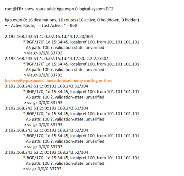
And finally bgp.evpn.0 on DC-2 is populated with relevant EVPN NLRI transmitted from DC-1 by using MP-BGP (family evpn signaling).

Hi
Contrail tunnels all traffic in GRE so you don’t need any L2 already inside one data center. The same should work between DCs with just a L3 DCI. Why do you need EVPN in this scenario at all? Basically, Contrail virtual network is already a EVPN.
LikeLike
MPLS over GRE is used for forwarding plane. Now we have requirement to connect 2 DCs and each have their own Contrail. So how control plane will work, both DCs need to learn each other MAC and IPs. Some mechanism must be there for control plane information exchange and EVPN is best option available.
LikeLiked by 1 person
Hello Sir,
I have fine with MPLSoGRE reference using this post.
But when I change tunnel type to udp, it is not working.
I want to know MPLSoUDP between MX router and contrails vrouter can use ?
LikeLike
Hello mate great bllog post
LikeLike
thanks Deacon
LikeLike