
1 Data Center Inter-Connect (DCI)
DCI was always a challenge in days of VPLS and other vendor specific layer 2 extension technologies. Main challenge was how and where to integrate layer 2 and layer 3 e.g VPLS does offer layer 2 extension between 2 DCs but main challenge was where to configure layer 3 gateways and how to maintain ARP entry for gateway inside a Virtual Machine (VM) if VM moves from once DC to another DC.
EVPN gives answer to all those questions as we can create MAC-VRF along with Integrated Routing and Bridging (IRB) interface for a VLAN and that IRB interface can also be referred under standard L3 VRF if L3 extension is required between DCs. Thus, EVPN allows to combines L2 and L3 at L3 VTEP layer. Furthermore, we can configure same “virtual-gateway” on all L3 VTEPs for a VLAN. This scenario will allow a VM to maintain the ARP entry for the gateways if it moves from one DC to another DC.
1.1 Option 1
In each Data Center “Collapsed IP CLOS” is recommended to be configured if DCI Option 1 is selected for Layer 2 extension between the DCs. One leaf node from each DC can be selected as DC gateway node and its loopback IP can be advertised to the other DC through existing L3 VPN. Once loopback IP address of remote DC gateway leaf node is reachable on the local DC gateway leaf node, over the top EVPN-VxLAN can be configured in usual manner.
At same time if there is a requirement to extend only layer 3 connectivity from a DC to another site, we need to advertise layer 3 gateways configured on leaf node toward core layer on overlay BGP session. Once layer 3 gateways are available on core layer same can be advertised toward PE router by use of any dynamic routing protocol. On PE router, these routes can be advertised to any remote site through L3 VPN.

1.2 Option 2
Control plane and Data Plane flow of sequence is as under: –
- VxLAN gateways are configured on core layer, VxLAN encapsulated packets arrives on core layer.
- Core layer will de-encapsulate VxLAN packets and will be forwarded VLAN tagged packets to PE router.
- On PE router VLAN tagged interfaces (connected to Data Center core layer) will be configured under MAC VRF.
- PE routers are configured to participate in MP-iBGP session along with EVPN signaling and MPLS based forwarding.
- APR entries arriving from Core layer on PE router for each VLAN will be shared with remote PE through EVPN based control plane.
- Once remote PE receive the EVPN type 2 routes, it will de-encapsulate EVPN routes and share it with te attached core layer as VLAN tag packets.
- The remote core layer will share the received Ethernet frames with leaf layer through IP-CLOS (EVPN-VxLAN based signaling and forwarding plane).
- Severs connected on both Data Centers will be able to communicate through MPLS based Data Plane running on Svc provider network, as their ARP entries have already been shared through EVPN based control plane.
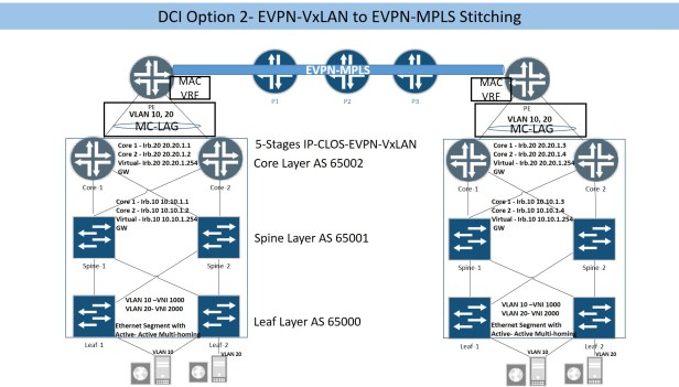
IP-CLOS configuration has been covered above in IP-CLOS section, only PE routers and Core routers uplink configuration will be explained here. Below snippet is showing Core-1 uplinks and MAC VRF configuration, Core-2 uplink and MAC VRF will be configued in same way. Each core router has one uplink connected with PE router, in order to depict both Core devices as single device on PE router, aggregate interfaces will be configued on Core router with same system ID and on PE router single aggregate link will be configured for the interfaces connected with core layer.
Interfaces {
xe-0/0/4 {
gigether-options {
802.3ad ae0;
}
}
}
ae0 {
description Connected-with-Core;
flexible-vlan-tagging;
encapsulation flexible-ethernet-services;
aggregated-ether-options {
lacp {
active;
system-id 00:55:00:44:55:00;
}
}
unit 10 {
family bridge {
interface-mode trunk;
vlan-id-list 10;
}
}
unit 20 {
family bridge {
interface-mode trunk;
vlan-id-list 20;
}
}
}
}
routing-instances {
tenat-1 {
vtep-source-interface lo0.0;
instance-type virtual-switch;
interface ae0.10;
interface ae0.20;
route-distinguisher 172.172.1.5:1;
vrf-import EVPN-IMPORT;
vrf-target target:1:10;
protocols {
evpn {
encapsulation vxlan;
extended-vni-list [ 1000 2000 ];
vni-options {
vni 1000 {
vrf-target target:10:1000;
}
vni 2000 {
vrf-target target:10:2000;
}
}
multicast-mode ingress-replication;
}
}
bridge-domains {
BD-10 {
vlan-id 10;
routing-interface irb.10;
vxlan {
vni 1000;
}
}
BD-20 {
vlan-id 20;
routing-interface irb.20;
vxlan {
vni 2000;
}
}
}
}
}
Below configuration snippet is taken from PE1 (left side Data Center), other side PE configuration will be same.
interfaces {
xe-0/0/0 {
gigether-options {
802.3ad ae0;
}
}
xe-0/0/1 {
gigether-options {
802.3ad ae0;
}
}
ae0 {
flexible-vlan-tagging;
encapsulation flexible-ethernet-services;
aggregated-ether-options {
lacp {
active;
}
}
unit 10 {
family bridge {
interface-mode trunk;
vlan-id-list 10;
}
}
unit 20 {
family bridge {
interface-mode trunk;
vlan-id-list 20;
}
}
}
MAC VRF needs to be configured on PE routers, MAC VRF configured in 5-Stages or 3-Stages IP-CLOS section is bit different from below configuration. PE routers are enabled for MPLS based forwarding so VxLAN encapsulation configuration is not required here.
routing-instances {
EVPN-MPLS {
instance-type virtual-switch;
interface ae0.10;
interface ae0.20;
route-distinguisher 173.173.173.1:1;
vrf-target {
import target:10:1000;
export target:10:1000;
}
protocols {
evpn {
extended-vlan-list [ 10 20 ];
}
}
bridge-domains {
BD-10 {
vlan-id 10;
}
BD-20 {
vlan-id 20;
}
}
}
}
1.3 Option 3
Control plane and Data Plane flow of sequence is as under: –
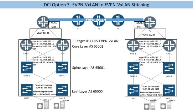
- VxLAN gateways are configured on core layer, VxLAN encapsulated packets arrives on core layer.
- Core layer will de-encapsulate VxLAN packets and will be forwarded VLAN tagged packets to PE router.
- On PE router VLAN tagged interfaces (connected to Data Center core layer) will be configured under MAC VRF.
- PE routers are configured to participate in MP-iBGP session along with EVPN signaling and MPLS based forwarding.
- APR entries arriving from Core layer on PE router for each VLAN will be shared with remote PE through EVPN based control plane.
- Once remote PE receive the EVPN type 2 routes, it will de-encapsulate EVPN routes and share it with te attached core layer as VLAN tag packets.
- The remote core layer will share the received Ethernet frames with leaf layer through IP-CLOS (EVPN-VxLAN based signaling and forwarding plane).
- Severs connected on both Data Centers will be able to communicate through VxLAN based Data Plane running on Svc provider network, as their ARP entries have already been shared through EVPN based control plane.
- The forwarding plane in Svc provider core network is based on VxLAN, which means on PE router we need to configured EVPN-Signaling with VxLAN forwarding.
It is possible to simulate Core and PE router in same MX device by creating 2 separate MAC-VRF, Ethernet packets from Core MAC-VRF can be extended till PE MAC-VRF by using logical tunnel (lt) interface. In this scenario, Virtual Network Identifiers (VNI) for each VxLAN used in both MAC-VRF must be different as same VNI cannot be used in more than one MAC-VRF.
5 stages IP-CLOS configuration will not be covered here as it is covered in detail in IP-CLOS section, extension of Ethernet frame from Core layer till PE router has also been covered above in “’DCI Option 2” section. Here we will cover only MAC-VRF configuration for PE router only to show how VxLAN based forwarding plane is configured in service provider network. There is no significance difference in MAC-VRF configuration on PE router and Core layer except the difference in VNI values (reason is explained in above paragraph).
routing-instances {
tenaet1 {
vtep-source-interface lo0.0;
instance-type virtual-switch;
interface ae0.10; Aggregate link toward Core router carrying Ethernet tagged frames
interface ae0.20;
route-distinguisher 173.173.173.1:1;
vrf-import EVPN-VXLAN;
vrf-target target:1:100;
protocols {
evpn {
encapsulation vxlan;
extended-vni-list [ 10000 20000 ];
vni-options {
vni 10000 {
vrf-target target:100:10000;
}
vni 20000 {
vrf-target target:100:20000;
}
}
multicast-mode ingress-replication;
}
}
bridge-domains {
BD-10 {
vlan-id 10;
vxlan {
vni 10000;
ingress-node-replication;
}
}
BD-20 {
vlan-id 20;
vxlan {
vni 20000;
ingress-node-replication;
}
}
}
}
}
Aggregate interface (carrying Ethernet tagged packets) toward Core layer is give below
interfaces {
ae0 {
flexible-vlan-tagging;
encapsulation flexible-ethernet-services;
aggregated-ether-options {
lacp {
active;
}
}
}
unit 10 {
encapsulation vlan-bridge;
family bridge {
interface-mode trunk;
vlan-id-list 10;
}
}
unit 20 {
encapsulation vlan-bridge;
family bridge {
interface-mode trunk;
vlan-id-list 20;
}
}
}
MAC-VRF and uplink configuration for Core layer is given below.
routing-instances {
tenat1 {
vtep-source-interface lo0.0;
instance-type virtual-switch;
interface ae0.10; Uplink interface carrying VLAN tagged packets towards PE router
interface ae0.20;
route-distinguisher 172.172.1.3:1;
vrf-import EVPN-IMPORT;
vrf-target target:1:10;
protocols {
evpn {
encapsulation vxlan;
extended-vni-list [ 1000 2000 ];
vni-options {
vni 1000 {
vrf-target target:10:1000;
}
vni 2000 {
vrf-target target:10:2000;
}
}
multicast-mode ingress-replication;
}
}
bridge-domains {
BD-10 {
vlan-id 10;
routing-interface irb.10;
vxlan {
vni 1000;
ingress-node-replication;
}
}
BD-20 {
vlan-id 20;
routing-interface irb.20;
vxlan {
vni 2000;
ingress-node-replication;
}
}
}
}
}
Each core router has one uplink connected with PE router, in order to depict both Core devices as single device on PE router, aggregate interfaces will be configued on Core router with same system ID.
Interfaces {
xe-0/0/4 {
gigether-options {
802.3ad ae0;
}
}
}
ae0 {
description Connected-with-Core;
flexible-vlan-tagging;
encapsulation flexible-ethernet-services;
aggregated-ether-options {
lacp {
active;
system-id 00:55:00:44:55:00;
}
}
unit 10 {
family bridge {
interface-mode trunk;
vlan-id-list 10;
}
}
unit 20 {
family bridge {
interface-mode trunk;
vlan-id-list 20;
}
}
}
}
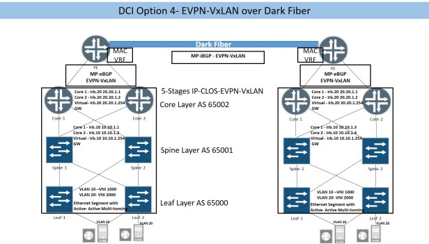
1.4 Option-4
Option 4 is used once dark fiber is available between 2 DCs, MP-iBGP with EVPN signaling and VxLAN forwarding plane can be configured. As there is no involvement with Svc provider network so it is matter of our own where to connect dark fiber and Data Center interconnect, it can be either between 2 border leaf nodes (one from each DC) or between PE routers.
If leaf nodes are selected for Data Center gateways, then configuration is covered in section above “DCI Option 1”. If PE routers are selected for DC gateways, then “DCI Option 3” section above covers the design considerations and configuration guidelines.
1.5 Conclusion
To select the appropriate DCI model needs deliberate considerations. The real challenge will be handling of EVPN routing entries by the FIB/RIB at Inter DC gateway nodes, as EVPN type 2 routes (MAC+IP) for each host inside a DC will be shared with other DC and each EVPN type 2 route has subnet mask of /304. Volume of EVPN 2 routes needs to be shared between 2 web scale Data Center for layer 2 DCI will be mammoth and have serious performance degradation impact on Inter DC gateway nodes. EVPN type 5 routes provide solution to this challenge. EVPN type 5 routes means we don’t use same subnet for a VxLAN in each DC so layer 2 extension is not required between the DCs. In this case, only IP subnets needs to be shared between DCs using EVPN control plane and no need for EVPN type 2 routes to be shared between DCs. EVPN type 5 routes implementation is not covered in this document.
