
")
Juniper Contrail is Software Defined Networking (SDN) controller which automate the network provisioning in a Virtual Data Center. In traditionally server hyper-visor environment there is still need to configure and allow VLANs on Data Center switches ports connected with servers, which involves inordinate delays due to lengthy “Change Process” approval and dependency on many teams. But modern centers can not afford such delays for service provisioning as delay in service provisioning means loss of revenue.
The scope of this blog is to discuss:-
- How physical servers can talk with servers deployed inside SDN environment.
- Layer 2 & Layer 3 Data Center Interconnect (DCI) solution between two enterprise Data Centers (DCs)

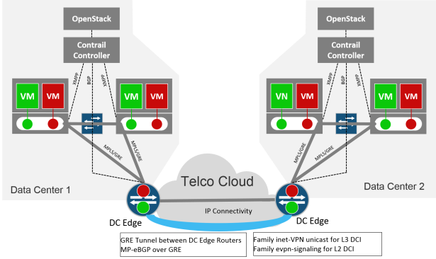
Above diagram shows architecture of Contrail , quick overview of Contrail inner working described below, please follow the link for Contrail in depth reading (http://www.opencontrail.org/opencontrail-architecture-documentation/)
- Contrail control node act as central brain.
- Contrail installs an instance of vRouter on each compute node.
- Each vRouter on a compute node creates separate VRF (Virtual Routing and Forwarding table) for each particular subnet for which a Virtual Machines are created.
- Full mesh MP-iBGP is configured by Contrail between itself and all vRouters, Overlay tunnels (MPLS over GRE, MPLS over UPD or VXLAN can be used to carry data plane traffic.
- Contrail Control node acts as Router Reflector in whole MP-iBGP domain.
Requirement 1:- Data base server which is installed on a physical compute machines needs to communicate with Application servers which are installed inside SDN environment.
Solution:
- Hence Contrail Control node as acting as Route Reflector (RR) for all vRouters running inside virtual environment. MP-iBGP between Contrail Controller and Gateway device will be configured.
- VRF will be configured on physical gateway with appropriate route-target community which should match with route-target community added on Contrail for particular subnet.
- VPN routes always looks in inet.3 (Junos) routing table for next hop resolution and inet.3 is normally populated through routes learned from MPLS LSPs (RSVP/ LDP). Inside Data Center it is not possible to signal MPLS LSPs particularly in terms of Contrail so we will configure dynamic GRE tunnels. These tunnel will populate inet.3 on physical gateway and thus fulfill the requirement of presence of VPN next hop in inet.3
- Physical servers which needs to talk with virtual world must have interface routes on gateway device (which means for this particular vlan RVI/ IRB must be configured on the gateway device). RVI/ IRB interface will be placed inside the VRF and statement”vrf-table-label” (Gateway is Juniper MX router) will configured inside VRF. It will cause automatic export of interface routes from that particular VRF after adding the route-target community.
- SDN controller will receive physical server routes through MP-iBGP and will re-advertised to all vRouters.
- Each vRouter will check the route-target community on the received routes to find any VRF with matching route-target and subsequently install the received routes into respective VRF.
- In this way end to end communication between SDN environment server and physical server will take place.
Requirement 2: L2 and L3 Data Center interconnect is required between two DCs who has their own SDN controller.
Solution:
- L3 Data Center is pretty simple and requirement can be fulfilled through traditional IP/VPN connection from service provider connection.
- Enterprises traditionally depends on Dark Fiber or on service providers for L2 extension (VPLS etc) between enterprises Data Center, hence both options involves plenty of cost.
- We will discuss a cost effective solution for L2 DCI, it is nor dependent on Dark Fiber and neither dependent on service provider solutions (VPLS etc)
- Between two Data Center we just need IP connectivity and by using that IP connectivity GRE based dynamic tunnels will configured between DCs.
- MP-eBGP will be configured between the DCs with families (inet-VPN unicast and evpn-signalling).
- Ethernet VPN is new techniques which enables MP-BGP to carry (MAC , ARP and VLAN IDs) thus allowing Layer 2 extension between Data Centers. Follow the following link to learn more about EVPN (https://tgregory.org/2016/06/04/evpn-in-action-1/ )
This blog only discussed high level architecture for DCI and gateway for SDN environment for deep dive into the topic please read my another blog.

Configuration on Data Center Edge router and Contrail Node is not added for brevity, if some one need configuration guidelines it can be shared.
LikeLike
Hello Sir, can you share me configuration?
I am now doing Physical Compute machines connect with Contrails VM.
I use net conf ssh add vMX router to contrails and testing but fails.
For DCI between Contrails, I want to know vMX is needed like CE router or Contrails Controller will act as CE?
I am using MPLS L3 VPN between Contrails now.
Please guide me.
LikeLike
hi Sat Aung, your 1st question is related to Device Manager functionality for that you need to go through contrail documentation. For DCI off course we need vMX or other gateway device. Controller to controller direct DCI connection is not possible.
LikeLike
Please sir..if you still have it, i would like to see the conf you made on both.
please share it.
LikeLike